
Connected type pressure-resistant flange plate

A one-piece, pressure-resistant technology, applied in flange connection, pipe/pipe joint/pipe fitting, through components, etc., can solve the problems of inconvenient installation, disassembly and maintenance, high use efficiency, long service life and reasonable design structure , the effect of high efficiency

Inactive Publication Date: 2016-07-27
JIANGSU LEADER PRECISION MACHINEY SALE CO LTD
View PDF6 Cites 0 Cited by
  • Summary
  • Abstract
  • Description
  • Claims
  • Application Information

AI Technical Summary

Problems solved by technology

[0006] Purpose of the invention: The purpose of the invention is to provide a one-piece pressure-resistant flange, which has a reasonable design structure and an integrally formed carbon steel structure, which has the characteristics of wear resistance, corrosion resistance and pressure resistance, and has a long service life and does not require High efficiency for frequent maintenance, and at the same time solves the problem of inconvenient installation, disassembly and maintenance in the assembly of existing mechanical drive parts or positioning parts, and has a wide range of applications

Method used


Image

  • Connected type pressure-resistant flange plate
  • Connected type pressure-resistant flange plate

Examples


Embodiment 1

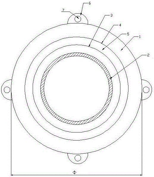
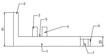
[0017] Such as figure 1 and figure 2 The shown one-piece pressure-resistant flange includes a flange body 1, a circular slot 2 arranged on the flange body 1, and a circular slot arranged on the flange body 1. 2 between the first limit ring 3, the second limit ring 4, wherein the diameter of the first limit ring 3 is smaller than the second limit ring 4, and is arranged on the first limit ring 3, the second limit ring The card groove 5 between the rings 4, and several positioning lugs 6 arranged on the outer surface of the flange body 1, and the positioning holes 7 respectively arranged in the positioning lugs 6; the flange body 1, the circular The card slot 2, the first limit ring 3, the second limit ring 4, the card slot 5 and the positioning ear plate 6 are integrally formed of carbon steel; the diameter of the flange body 1 is 230mm-240mm, and the flange The height H of the body 1 and the circular slot 2 is 70mm-80mm, and the height H1 of the positioning lug 6 is 20mm-30...

Embodiment 2

[0021] Such as figure 1 and figure 2 The shown one-piece pressure-resistant flange includes a flange body 1, a circular slot 2 arranged on the flange body 1, and a circular slot arranged on the flange body 1. 2 between the first limit ring 3, the second limit ring 4, wherein the diameter of the first limit ring 3 is smaller than the second limit ring 4, and is arranged on the first limit ring 3, the second limit ring The card groove 5 between the rings 4, and several positioning lugs 6 arranged on the outer surface of the flange body 1, and the positioning holes 7 respectively arranged in the positioning lugs 6; the flange body 1, the circular The card slot 2, the first limit ring 3, the second limit ring 4, the card slot 5 and the positioning ear plate 6 are integrally formed of carbon steel; the diameter of the flange body 1 is 235mm, and the flange body 1 The height H of the circular draw-in slot 2 is 75mm, and the height H1 of the positioning ear plate 6 is 25mm.

[00...


PUM


Abstract

The invention belongs to the technical field of mechanical drive part or positioning part assembly accessory application and particularly discloses a connected type pressure-resistant flange plate. The connected type pressure-resistant flange plate comprises a flange plate body, a round clamping groove formed in the flange plate body, a first limiting ring, a second limiting ring, a clamping groove arranged between the first limiting ring and the second limiting ring, a plurality of positioning lug plates arranged on the outer circle face of the flange plate body, and positioning holes formed in the positioning lug plates, wherein the first limiting ring and the second limiting ring are arranged between the flange plate body and the round clamping groove; and the diameter of the first limiting ring is smaller than that of the second limiting ring. The connected type pressure-resistant flange plate has the beneficial effects that the design and the structure are reasonable, an integrally-formed carbon steel structure has the characteristics of being resistant to abrasion, corrosion and pressure, the service life is long, frequent overhaul is not needed, and the using efficiency is high; and the problem that in assembling of an existing mechanical drive part or positioning part, installing, disassembly and maintenance are not convenient is solved, and especially in assembling of a speed reducer, the application range is wide.

Description

technical field [0001] The invention belongs to the technical field of assembly and application of mechanical drive components or positioning components, and in particular relates to a one-piece pressure-resistant flange, which is suitable for fast, accurate and stable assembly operations of mechanical drive components or positioning components. Background technique [0002] Flange is otherwise known as flange flange or flange. Flanges are parts that are connected to each other between pipes and are used for connection between pipe ends; they are also useful for flanges on equipment inlets and outlets, And can be used as connection between two equipments, example reducer flanges. Flange connection or flange joint refers back to the detachable connection of flange, Gasket and bolt as a team of combined sealing structure. Pipe flange refers back to the flange used for piping in the pipeline installation, And used on the equipment refers to the inlet and outlet flange of the e...

Claims


Application Information

Patent Timeline
Patent Type & Authority Applications(China)
IPC IPC(8): F16L23/032
CPCF16L23/032
Inventor 陆斌陆寅鹏
Owner JIANGSU LEADER PRECISION MACHINEY SALE CO LTD
Learn More