Fume afterheat recovering system by hidden heat process

A technology for waste heat and heat recovery from flue gas, applied in air heaters, fluid heaters, heat exchanger types, etc., can solve problems such as troublesome installation and maintenance on site, decrease heat exchange efficiency, affect combustion, etc., and achieve good environmental protection effects. , easy installation and maintenance, and the effect of reducing pollution

Inactive Publication Date: 2005-01-12
杨振东
View PDF1 Cites 12 Cited by
  • Summary
  • Abstract
  • Description
  • Claims
  • Application Information

AI Technical Summary

Problems solved by technology

Taking oil field associated natural gas as fuel to heat the heating medium mixed with water in a tube furnace as an example, the natural gas consumption in winter is 3100 cubic meters per day, and the exhaust gas temperature reaches above 310 ° C, while in summer, the natural gas consumption is 1900 cubic meters / day, the exhaust gas temperature is about 200℃, the heat load of the heating furnace is constantly changing, and the temperature and calorific value of the exhaust gas also change accordingly. Because the traditional heat exchange devices are fixed components, the heat exchange power is fixed, so it is very It is difficult to keep the flue gas temperature above the dew point temperature before and after heat exchange in such an environment, and it is not economical to do so. Therefore, traditional heat exchange devices and methods have fatal weaknesses of low efficiency and short life; Corrosion-resistant materials can certainly overcome the problem of dew point corrosion, but the exhaust gas temperature of general heating furnaces, especially tube furnaces fueled by oilfield associated natural gas, is above 250°C, which is far beyond the operating temperature range of economical corrosion-resistant materials.
If the metal heat exchange element and the corrosion-resistant heat exchange element are used in series, the flue gas temperature must be kept between the dew point corrosion temperature and the online service temperature of the corrosion-resistant heat exchange element after passing through the metal heat exchange element and before the corrosion-resistant heat exchange element. In the narrow range between, because it is difficult to achieve in actual production, it is rarely used
In addition, traditional heat exchange devices have the problem of reduced heat exchange efficiency due to fouling and ash deposition, so it is necessary to design a descaling and ash removal device for heat exchange components
The tube furnaces widely used in oil fields are all natural ventilation. If you don’t want to change the original ventilation mode of the heating furnace, you must install the heat exchanger on the top of the heating furnace. In this way, the force structure of the heating furnace must go through a complicated process. Recalculate and Retrofit
Because it is installed on the top of the heating furnace, it will inevitably cause a lot of trouble for the on-site installation and future maintenance of the device
Since it is natural ventilation, it is required that the heat exchange components cannot cause too much pressure drop in the pipeline. The heat exchange efficiency is proportional to the heat exchange area. From this perspective, this structure must be inefficient.
If the natural ventilation is transformed into forced ventilation, once the fan is out of operation due to failure or power failure, it will inevitably affect the combustion; in addition, once the tube furnace fueled by associated natural gas loses ventilation, it may explode in an instant. production accident

Method used


Image

  • Fume afterheat recovering system by hidden heat process

Examples


Embodiment Construction

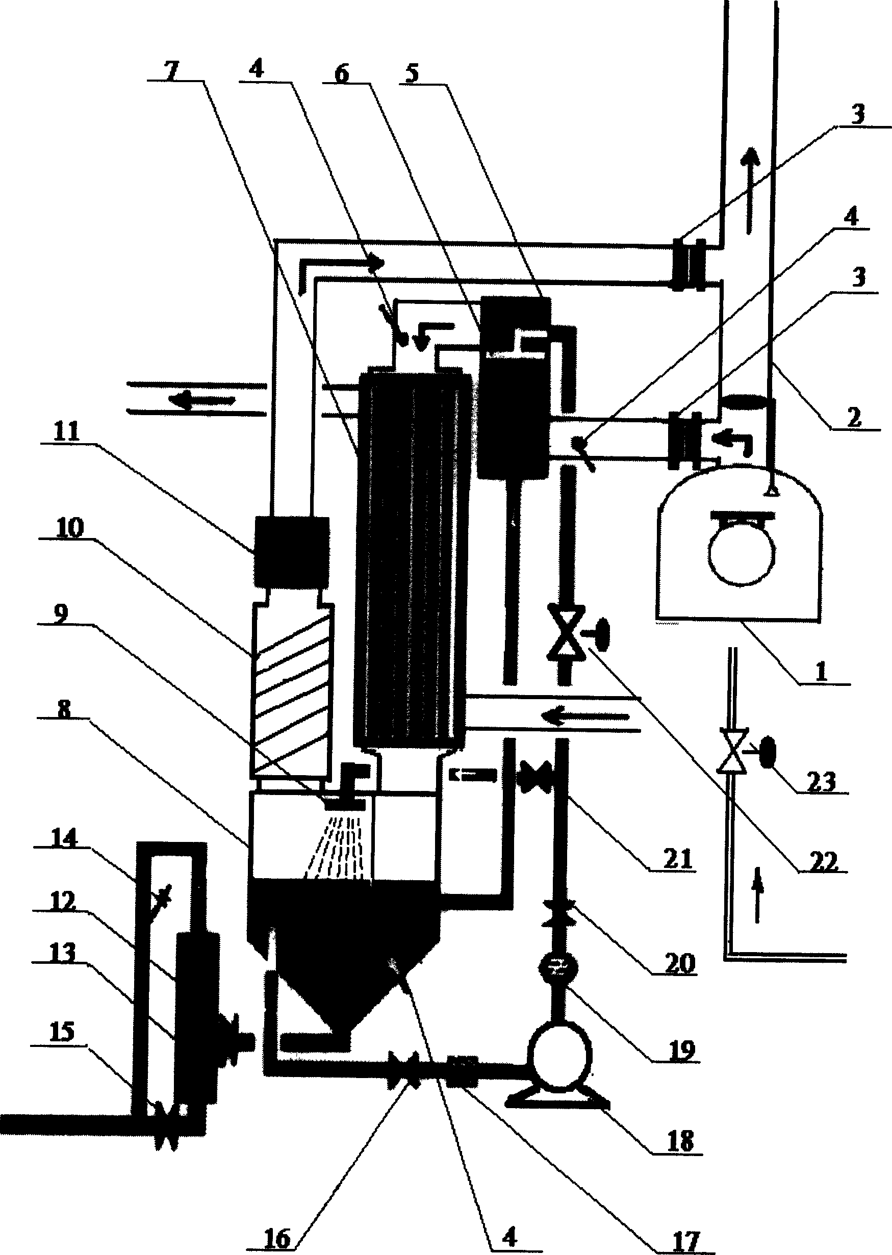
[0021] The specific embodiment of the present invention will be further described below in conjunction with the accompanying drawings:

[0022] Recovery device chimney 2, temperature sensor 4, spray cooling tower 5, sprayer 6, heat exchanger 7, acid tank 8, sprayer 9, mist trapping tower 10, The induced draft fan 11, the ash tank 13, the pump 18, and the automatic regulating valve 22 are composed. The upper and lower ends of the baffle plate of the chimney 2 are respectively provided with a flue gas outlet and a flue gas inlet. The flue gas outlet is connected to the spray cooling tower 5 by a pipeline. The temperature sensor 4 is installed on the pipeline entering the spray cooling tower 5 to monitor the temperature of the flue gas entering the spray cooling tower 5 . The spray cooling tower 5 is a steel shell lined with acid-resistant ceramics. There is a medium spray device composed of a sprinkler 6 as the main component in the tower. The outlet of the tower is connected to...


PUM


Abstract

The method includes heat conversion, and heat recovery two procedures: (1) in first procedure, high temperature fume from flue enters into sprinkling cooling tower, where sprinkling media contact to fume. Media are vaporized. Thus, sensible heat in fume is transferred to latent heat; (2) media and fume enter into acid resistant heat exchanger. Media are condenses to release latent heat exchanged to media needed to heat. The recovery system is composed of temp sensor, sprinkling cooling tower, heat exchanger, pump and automatic control valve etc. Features are: compact, lightweight, high reclaiming efficiency.

Description

Technical field: [0001] The present invention relates to a device and method for recovering flue gas waste heat, especially the recovery and utilization of flue gas waste heat of tube furnaces that use oilfield associated natural gas as fuel, and is also applicable to other industrially valuable power plants such as coal as fuel Recycling of flue gas waste heat. Background technique: [0002] There are three kinds of fuels commonly used in existing heating furnaces, coal, fuel oil, and natural gas. Regardless of which fuel is used, the heat loss caused by exhaust smoke accounts for more than 80% of the heat loss of the heating furnace. [0003] At present, the more common method of industrial flue gas waste heat recovery is that the heat exchange element directly exchanges heat with the flue gas, and different heat exchange elements are selected for different temperature ranges. The heat exchange elements involved in the heat exchange device are: 1. Metal 2. Heat exchange e...

Claims


Application Information

Patent Timeline
Patent Type & Authority Applications(China)
IPC IPC(8): F24H8/00F28C3/08
CPCY02B30/102Y02B30/00
Inventor 杨振东
Owner 杨振东
Why Eureka
Try Eureka