Low pollution power generation system with ion transfer membrane air separation

a technology of ion transfer membrane and power generation system, which is applied in the direction of efficient propulsion technology, machines/engines, light and heating apparatus, etc., can solve the problems of reducing the number of cars and miles driven, and preventing the emission of air pollutants. achieve the effect of nitrogen oxides

Inactive Publication Date: 2005-09-20
CLEAN ENERGY SYST
View PDF218 Cites 171 Cited by
  • Summary
  • Abstract
  • Description
  • Claims
  • Application Information

AI Technical Summary

Benefits of technology

[0021]Another object of the present invention is to provide a combustion based power generation system which includes an air treatment plant for separating nitrogen from the air prior to use of the air to combust a hydrocarbon fuel, such that nitrogen oxides are reduced or eliminated as byproducts of combustion in the power generation system.

Problems solved by technology

The major source of this vehicle pollution comes from passenger cars and light to medium duty trucks.
No near term solutions appear in sight to drastically reduce the vast amount of air pollutants emitted by the many millions of automobiles and trucks operating today.
Also, the number of cars and miles that are being driven continue to increase, further hampering efforts to reduce smog causing pollutants.
These allowable emission reductions are placing severe demands on the transportation industry and the electric power generating industry to develop new and lower emission power systems.
However, widespread use of these energy sources for vehicles and for electric power generating facilities do not appear to yet be practical.

Method used


Image

  • Low pollution power generation system with ion transfer membrane air separation
  • Low pollution power generation system with ion transfer membrane air separation
  • Low pollution power generation system with ion transfer membrane air separation

Examples


first embodiment

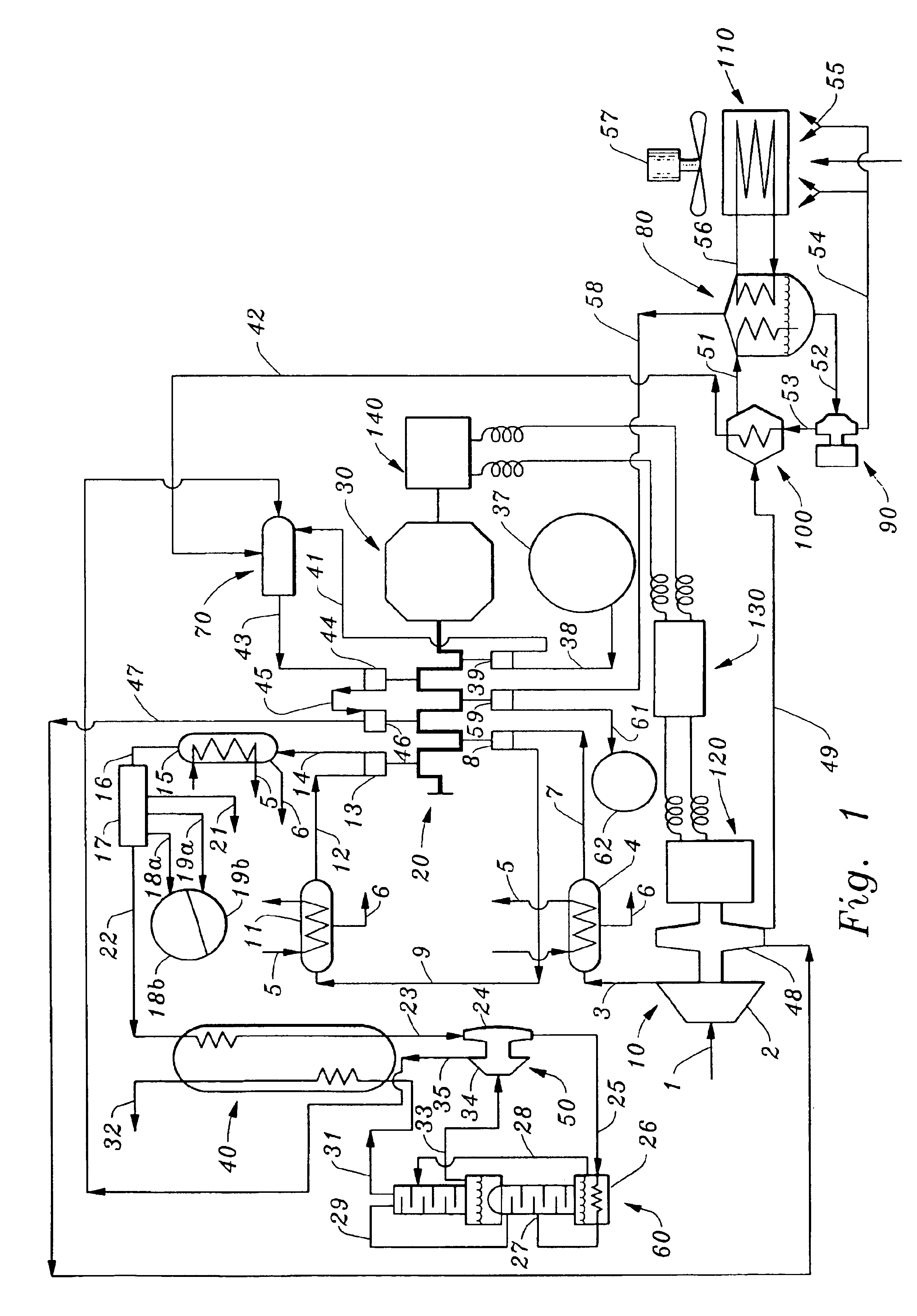
[0046]According to the present invention, a zero or very low pollution Rankine cycle thermal engine operating in parallel with a zero emissions electric motor (also referred to as a hybrid engine) is illustrated in FIG. 1. The Rankine engine consists of a dynamic turbocompressor 10, a reciprocating engine 20, a power transmission 30, a heat exchanger 40, a turboexpander 50, a rectifier 60, a gas generator 70, a condenser 80, a recirculating water feed pump 90, a water heater 100 and a condenser coolant radiator 110. The electric engine consists of an alternator 120, a battery 130 and electric motor 140.

[0047]Hybrid engine operation begins by starting the electric motor 140 using the battery 130 as the energy source. The electric motor 140 drives the reciprocating engine 20 through the power transmission 30 and thereby initiates the start of the thermal engine that requires a chill-down period for the liquefaction equipment consisting of heat exchanger 40, turboexpander 50 and rectif...

sixth embodiment

[0054]Following the complete combustion of the high temperature gases, recirculating water is injected into the gas generator 70 through line 42 and dilutes the high temperature gases to a lower temperature drive gas acceptable to the reciprocating engine (approximately 2000° R). This water influx also increases a mass flow rate of combustion products available for expansion and power generation. The drive gas then exits the gas generator 70 through discharge duct 43, enters reciprocating cylinder 44, expands and provides power to the power transmission 30. Other combustion product expansion devices can replace the reciprocating cylinder 44, such as the dynamic turbines discussed in the sixth embodiment below. The gas exits through duct 45, enters the second cylinder 46, expands and also provides power to the power transmission; the gas exits through duct 47 and powers the dynamic turbine 48 which drives the centrifugal compressor 2, which was driven by the electric motor 140 during...

second embodiment

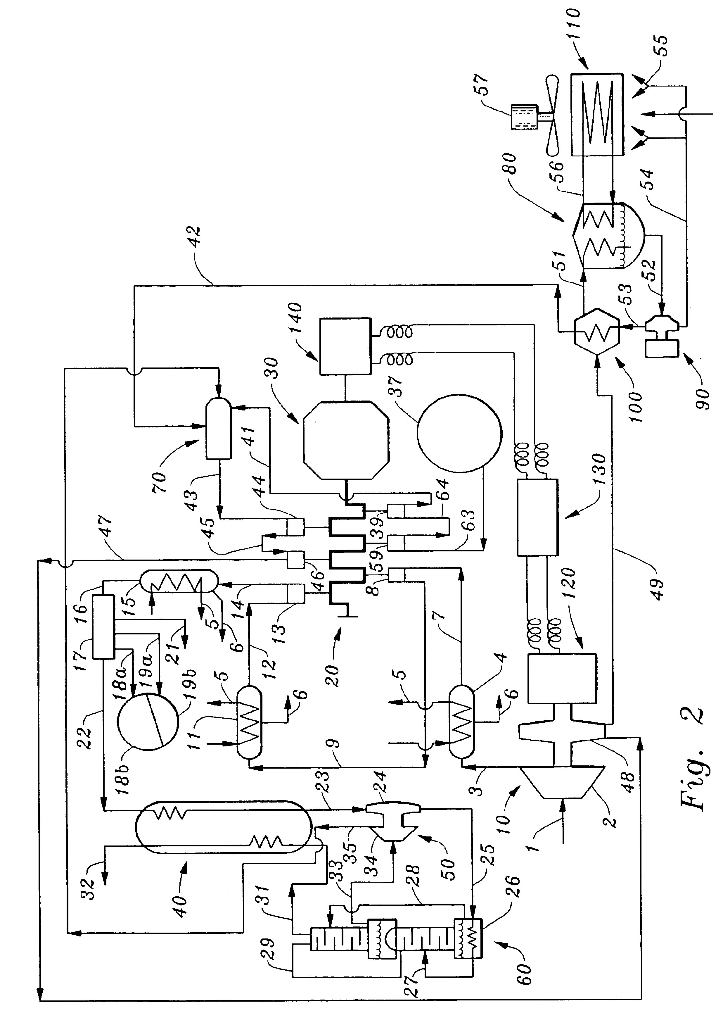
[0058]this invention, illustrated in FIG. 2, features a hybrid engine when using hydrogen in place of a hydrocarbon fuel. When using hydrogen as the fuel no carbon dioxide is generated and only high purity steam exits from the gas generator 70. Consequently all systems related to carbon dioxide are deleted, and no other changes are basically required. However, to maintain the same six cylinder engine of FIG. 1, the hydrogen fuel FIG. 2 exits the fuel supply tank 37 through duct 63, enters reciprocating engine cylinder 59, exits through duct 64, enters reciprocating engine cylinder 39, exits through duct 41 and is delivered to the gas generator 70. This permits two stages of compression for the low density hydrogen.


PUM


Abstract

A low or no pollution power generation system is provided. The system has an air separator to collect oxygen. A gas generator is provided with inputs for the oxygen and a hydrocarbon fuel. The fuel and oxygen are combusted within the gas generator, forming water and carbon dioxide. Water or other diluents are also delivered into the gas generator to control temperature of the combustion products. The combustion products are then expanded through at least one turbine or other expander to deliver output power. The combustion products are then passed through a separator where the steam is condensed. A portion of the water is discharged and the remainder is routed back to the gas generator as diluent. The carbon dioxide can be conditioned for sequestration. The system can be optimized by adding multiple expanders, reheaters and water diluent preheaters, and by preheating air for an ion transfer membrane oxygen separation.

Description

CROSS-REFERENCE TO RELATED APPLICATIONS[0001]This application claims benefit under Title 35, United States Code §119(e) of U.S. Provisional Application Nos. 60 / 426,866, 60 / 426,941 and 60 / 426,942 filed on Nov. 15, 2002.FIELD OF THE INVENTION[0002]This invention contains environmentally clean engine designs that emit zero or very low pollutant levels during operation. The CLEAN AIR ENGINE (CLAIRE) invention is directly applicable to both transportation type vehicles including automobiles, trucks, trains, airplanes, ships and to stationary power generation applications. The designs feature hybrid, dual cycle and single cycle engines.BACKGROUND OF THE INVENTION[0003]The current art in generating power for transportation purposes basically utilize the internal combustion gas or diesel engine. The current art for electric power generation utilize gas turbines and / or steam turbines. These devices burn hydrocarbon fuels with air which contains (by weight) 23.1% oxygen, 75.6% nitrogen and th...

Claims


Application Information

Patent Timeline
Patent Type & Authority Patents(United States)
IPC IPC(8): F02C3/20F02C6/10F02C3/30F02C6/00F01K25/00F02C1/08F25J3/04
CPCF01K25/005F25J3/04987F02C3/20F02C3/30F02C3/34F02C6/003F02C6/10F25J3/04018F25J3/04066F25J3/04109F25J3/04121F25J3/04127F25J3/04133F25J3/04139F25J3/04163F25J3/04296F25J3/04412F25J3/04533F02C1/08F05D2270/08F25J2200/52F25J2205/30F25J2230/80F25J2260/80Y02E20/34Y02T50/60
Inventor VITERI, FERMIN
Owner CLEAN ENERGY SYST
Why Eureka
Try Eureka