
Network architecture for wirelessly interfacing sensors at ultra low power

a sensor and wireless technology, applied in the field of wireless architecture, can solve the problems of increasing the complexity of the measurement apparatus, difficult to measure a physical parameter, and difficult vacuum measurement, etc., and achieve the effect of reducing design complexity and size, limiting or reducing power consumption

Inactive Publication Date: 2010-12-09
UNIVERSITE CATHOLIQUE DE LOUVAIN
View PDF9 Cites 22 Cited by
  • Summary
  • Abstract
  • Description
  • Claims
  • Application Information

AI Technical Summary

Benefits of technology

[0013]It is an object of the present invention to provide a new architecture that allows for interfacing sensors while limiting or reducing the power consumption and reducing design complexity and size. A first aspect of the invention provides:
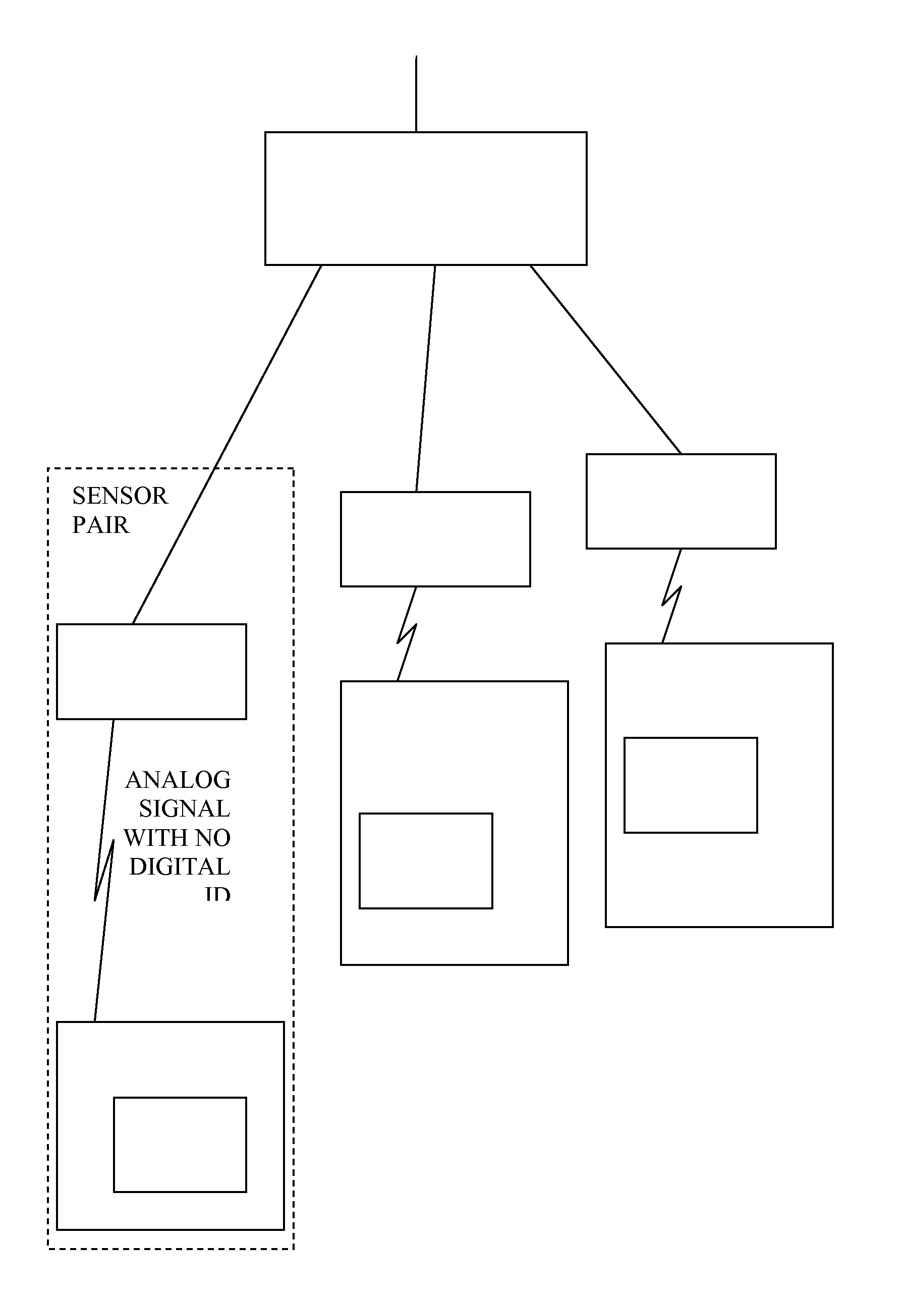
[0015]By providing a dedicated reader for each transponder, there is no need for the dedicated reader to distinguish between signals from other transponders. Other transponders would be located too far away to cause interference. This means the dedicated readers do not need to have circuitry to demodulate a digital identifier. This enables the dedicated readers to be simpler, cheaper and have lower power consumption. Indeed some of the more complex circuitry or function is moved upstream to the multiplexing reader.
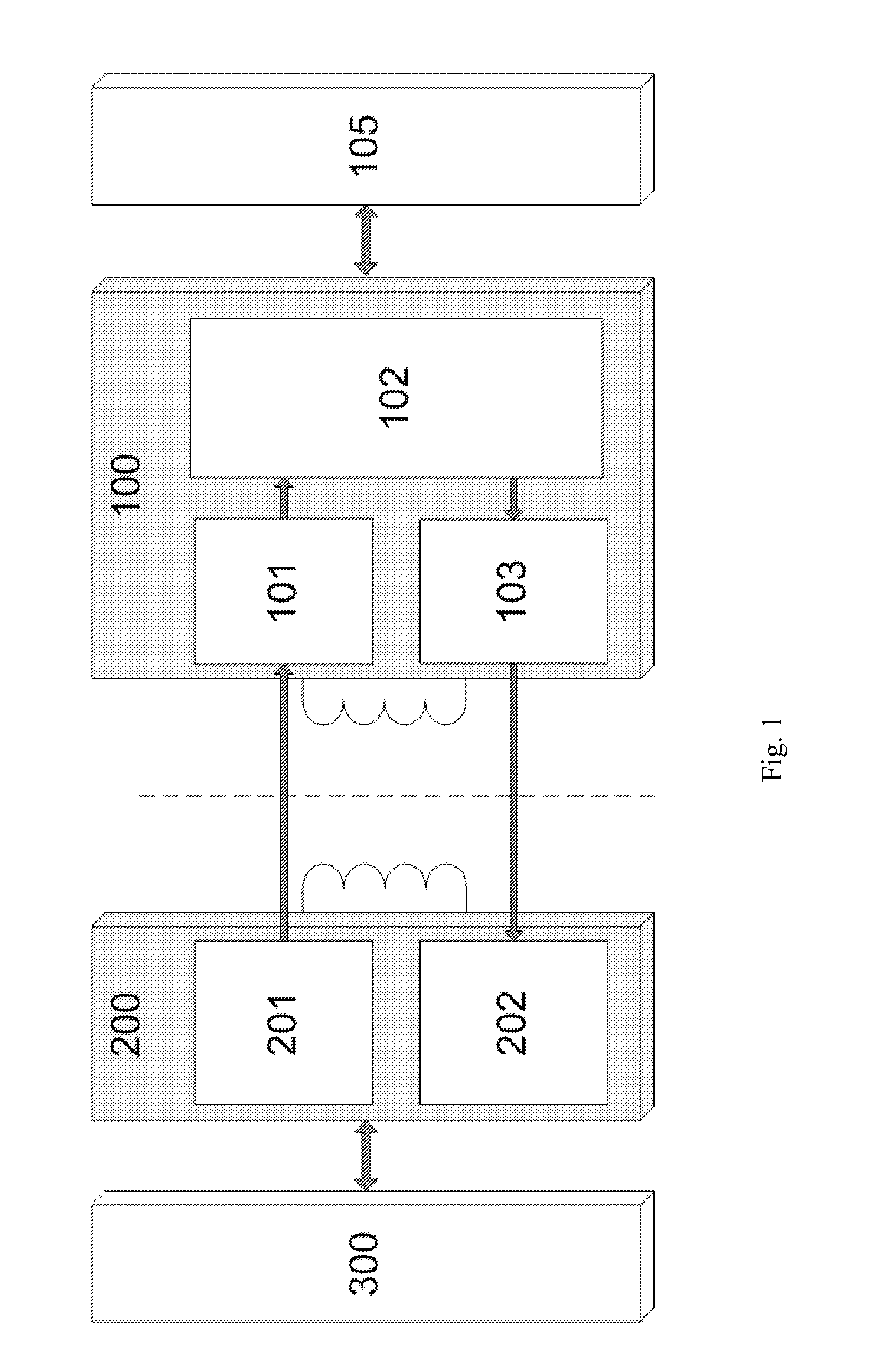
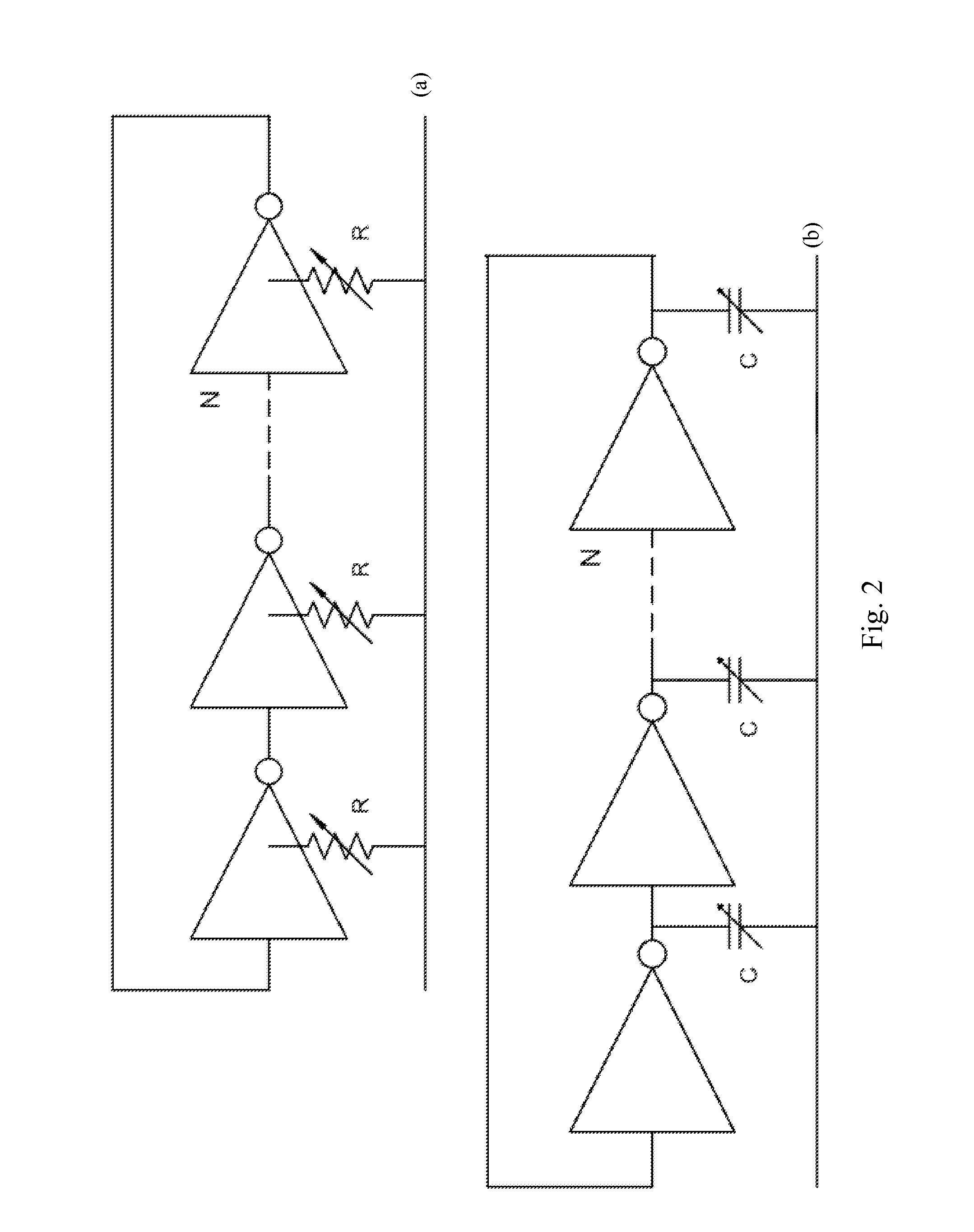
[0016]According to another aspect of the invention, the dedicated reader is arranged to send the sensing information to the multiplexing reader in analog or digital form, moreover using an analog or digital ID code. In one embodiment, the analog ID code can be a frequency provided by a free running oscillator. In any case, this effectively moves the optional digital demodulation interface upstream to the multiplexing reader, which brings similar advantages. The wireless interface may be an RF interface of the inductive or capacitive coupling type. The architecture is adapted to send analog data from a transponder to its dedicated reader. This analog data, coming from the transponder, is provided either by one or more sensing devices such as MEMS sensors, or is first retained or stored in a suitable analog memory before transmission. Any suitable memory can be used, e.g. a physical memory such as a capacitance, a resistance or a current value. Preferably this analog data is sent by the transponder to its dedicated reader at a short distance (to reduce power demands), e.g. via an inductive link, and using, on the dedicated reader side the carrier wave (Vin) frequency giving the higher possible efficiency according to the medium separating the transponder and the given dedicated reader. So, the frequency used can be different for each sensor pair in order to optimize the system. The inductive link preferably consumes very low power. The data may be transmitted via amplitude, phase, frequency modulation, or a combination of those for example.

Problems solved by technology

There are many situations where it is difficult to measure a physical parameter, for example the temperature in a test-tube without disturbing its content.
In the same way, measurements realized in vacuum can also be very difficult.
These measurements can be realized nowadays, but the price to pay is the increased complexity of the measurement apparatus.
There are also difficulties linked to measurements realized on rotating objects such as shafts.
Another solution requires a reader and a transponder coil located around the shaft, resulting in a bulky solution complex to implement.
One key aspect of portable electronic systems is power consumption.
Indeed, a high IC (Integrated Circuit) power consumption reduces its autonomy for systems working on batteries and increases its cost.

Method used


Image

  • Network architecture for wirelessly interfacing sensors at ultra low power
  • Network architecture for wirelessly interfacing sensors at ultra low power
  • Network architecture for wirelessly interfacing sensors at ultra low power

Examples


Embodiment Construction

[0031]Embodiments of the present invention will be described in detail with respect to certain drawings but the invention is not limited thereto. For illustrative purposes, most of the drawings are schematic, therefore, the size of the elements are not drawn to scale. Where the term “comprising” is used in the present description and claims, it does not exclude other elements or steps. Where an indefinite or definite article is used when referring to a singular noun e.g. “a” or “an”, “the”, this includes a plural of that noun unless something else is specifically stated.

[0032]The term “comprising”, used in the claims, should not be interpreted as being restricted to the means listed thereafter; it does not exclude other elements or steps. Thus, the scope of the expression “a device comprising means A and B” should not be limited to devices consisting only of components A and B. It means that with respect to the present invention, the only relevant components of the device are A and ...


PUM


Abstract

A sensing network is described, consisting of a multiplexing reader and one or more sensor pairs, each sensor pair comprising a transponder and a dedicated reader, dedicated to that transponder, each transponder having a sensor. Each sensor pair is able to wirelessly interface and power both capacitive and resistive sensors at a short distance with high efficiency. By providing a dedicated reader for each transponder, each link can be optimized and there is no need for the dedicated reader to distinguish between signals from other transponders. The transponder generates an analog signal directly using a sensor or analog memory value and sends it by modulation to the dedicated reader. So, the dedicated readers do not need to have circuitry to demodulate a digital signal or ID code. The transponder includes the sensors and their electronic circuits and can be optionally remotely powered by the dedicated reader through the wireless link. The expected consumption of the dedicated reader can be lower than 200 μW.

Description

TECHNICAL FIELD[0001]The present invention relates to a wireless architecture including sensors, like sensors integrated in a remote tag for example, and methods of making and operating the same. In particular the present invention relates to Micro-Electro-Mechanical-Systems (MEMS), especially MEMS sensors.BACKGROUND[0002]There are many situations where it is difficult to measure a physical parameter, for example the temperature in a test-tube without disturbing its content. Indeed, sample volumes inside of it usually being very small, a very small sensor requiring no wired connection, directly plunged into the contents appears as a very elegant and innovative solution in the medical area.[0003]Another portable medical application concerns health monitoring for which a high efficiency is required along with a long range data transfer without perturbing the human body.[0004]In the same way, measurements realized in vacuum can also be very difficult. These measurements can be realized...

Claims


Application Information

Patent Timeline
IPC IPC(8): G08B9/00
CPCG08C19/12G08C2201/20H04Q2209/50H04Q9/00H04Q2209/47G08C2201/91
Inventor GOSSET, GEOFFROY PASCAL M.FLANDRE, DENISDELMEE, GILLESRUE, BERTRAND
Owner UNIVERSITE CATHOLIQUE DE LOUVAIN
Learn More