Powered nose aircraft wheel system

a technology of aircraft wheels and aircraft, which is applied in the direction of skis/runners, energy-saving operational measures, aircraft braking arrangements, etc., can solve the problems of aircraft repair costs, aircraft maneuvering during ground operations can pose significant expense, fuel costs, noise reduction costs, etc., to improve the efficiency and productivity of ground operations, reduce ground operational fuel costs, noise, air and ground water pollution, and improve the effect of arrival and departure efficiency and productivity

Inactive Publication Date: 2008-11-04
THE BOEING CO
View PDF46 Cites 199 Cited by
  • Summary
  • Abstract
  • Description
  • Claims
  • Application Information

AI Technical Summary

Benefits of technology

[0008]Another embodiment of the present invention provides a method of taxiing an aircraft, from the terminal gate to a place where the main engines can be powered up for takeoff, or to a place where the main engines can be shutdown after landing. Power is transferred from the auxiliary power unit of the aircraft to the wheel motor via a motor controller. The wheel is rotated via the wheel motor. The aircraft is steered and the speed of the wheel is controlled via one or more controllers. Steering and speed are regulated either by the onboard control of the pilot or by signals transmitted to the motor and steering controller by offboard systems. The method permits each aircraft nose landing gear wheel to freely spin during the landing or takeoff of the aircraft. The basic control function is based on pilot input. However, external commands may be inputted to the controller.
[0009]The embodiments of the present invention provide several advantages. One such advantage is the provision of landing gear wheel motors that allow a pilot or a remotely located control system to control the gate and taxiing environment of an aircraft without use of the aircraft main engines. This improves arrival and departure efficiency and productivity of ground operations. This also reduces ground operational fuel costs, noise, air and ground water pollution, labor expenses, aircraft damage from discrete source impacts with other vehicles, gate time, damage due to jet blast, and eliminates the need for tug operations. Elimination of ground support equipment also increases available gate space for more efficient use of airport facilities.
[0010]Furthermore, another advantage provided by multiple embodiments of the present invention is the provision of landing gear wheel motors that allow associated wheels to freely spin during high-speed operations and to engage with the motors during low-speed operations. High-speed operations may refer to when the aircrafts speed overdrives the motor speed, which may be realized by virtue of an automatically disengaged cone clutch mechanism. The wheel motors may be used as generators or to some degree as brakes during high-speed operations or when reduced wheel speed is desired to capture and store energy. The stored energy may be utilized during peak demand situations, such as during a breakaway motion or during aircraft acceleration. The wheel motors may be used as a driving source during low-speed operations. The wheel motors may also be operated to pre-spin the tires prior to landing, thereby, reducing wear and high torsional inertia loads on the nose landing gear, tires, and wheel motor assembly.
[0011]Yet another advantage provided by an embodiment of the present invention is the provision of an integrated operational ground support system that remotely controls ground maneuvering of multiple aircraft via a single control source. This advantage allows the orchestration of the total mobility of all aircraft in motion at an airport, which facilitates the adoption of closer standards of separation while yet providing a greater margin of safety. This has a beneficial effect upon the overall airport throughput and allows for better operating margins for the user airlines while mitigating the degree of future airport expansion programs.

Problems solved by technology

Aircraft maneuvering during ground operations can pose a significant expense in terms of fuel costs, emission costs, noise reduction costs, repair costs due to damage caused by jet blast, costs due to aircraft colliding with ground equipment, aircraft repair costs associated with damage caused by current taxiing procedures, personnel, and equipment, and labor costs for ground personnel and tug operations.

Method used


Image

  • Powered nose aircraft wheel system
  • Powered nose aircraft wheel system
  • Powered nose aircraft wheel system

Examples


Embodiment Construction

[0025]In each of the following Figures, the same reference numerals are used to refer to the same components. While the present invention is described with respect to systems and methods of controlling ground operation and taxiing of an aircraft, the present invention may be adapted for various applications and systems including: aeronautical systems, land-based vehicle systems, or other applications or systems known in the art that require similar control.

[0026]In the following description, various operating parameters and components are described for one constructed embodiment. These specific parameters and components are included as examples and are not meant to be limiting.

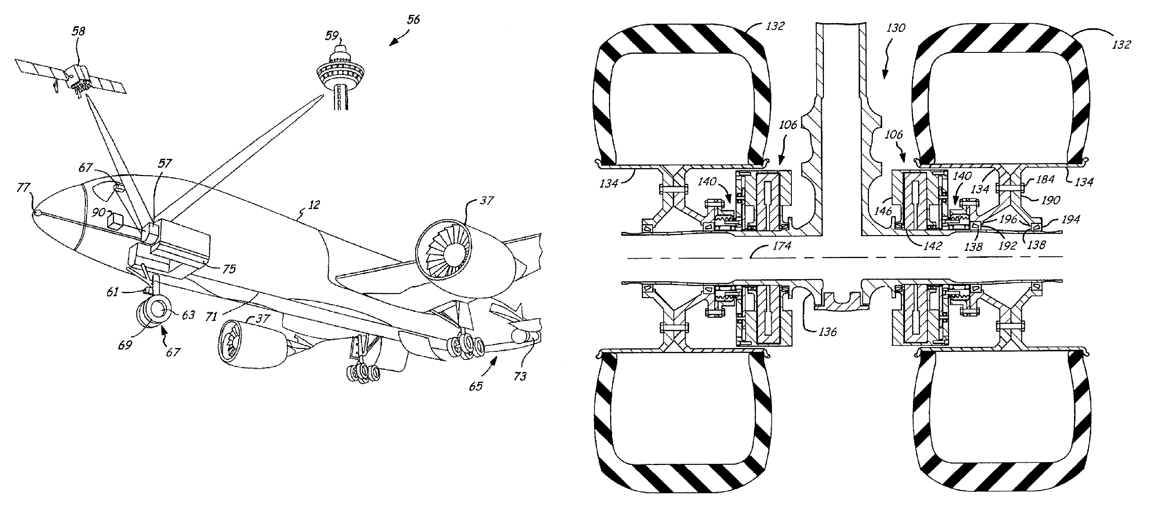
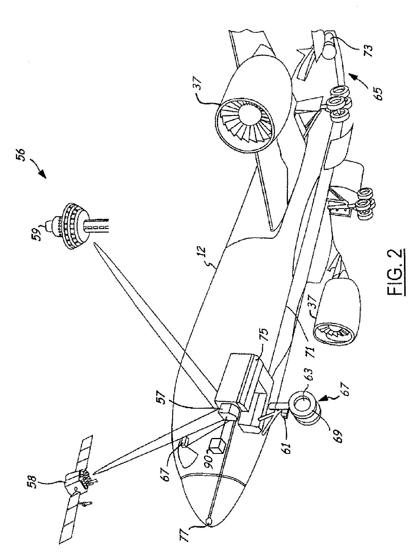
[0027]Also, in the following description the term “wheel motor” refers to any motor that is directly coupled to and is used to rotate a wheel. A main turbine engine of an aircraft that is separately coupled to the aircraft and is used for in flight operation would not be considered a wheel motor. The reference...


PUM


Abstract

A powered nose aircraft wheel system (130) for an aircraft (12) includes landing gear (104) that extends from the aircraft (12). A wheel axel (136) is coupled to the landing gear (104). A wheel (134) is coupled to the wheel axel (136). A wheel motor (106) is coupled to the wheel axel (136) and the wheel (134). A controller (120) is coupled to the wheel motor (106) and rotates the wheel (134). A method of taxiing an aircraft (12) includes permitting the wheel (134) of the aircraft (12) to freely spin during the landing of the aircraft (12). Power is transferred from an auxiliary power unit (73) of the aircraft (12) to the wheel motor (106). The wheel (134) is rotated via the wheel motor (106). The aircraft (12) is steered and the speed of the wheel (134) is controlled via one or more controllers selected from an onboard controller (18, 118, 120) and an offboard controller (45, 58, 59).

Description

RELATED APPLICATION[0001]The present application is a continuation-in-part (CIP) of U.S. patent application Ser. No. 10 / 711,610, filed Sep. 28, 2004, entitled “OPERATIONAL GROUND SUPPORT SYSTEM”, which is incorporated by reference herein.TECHNICAL FIELD[0002]The present invention relates generally to aeronautical vehicle ground support systems and automated controlled ground mobility. More particularly, the present invention relates to integrated systems and methods of providing controlled mobility during ground taxi of an aircraft.BACKGROUND OF THE INVENTION[0003]It is desirable within the airline industry to provide efficient aircraft servicing and ground mobility. Time involved in taxiing to and from gates and in performing various servicing tasks, is directly related to the amount of time an aircraft is able to spend in flight. The more an aircraft is in flight the higher the potential profits associated with that aircraft.[0004]Aircraft taxing to and from a gate is typically ac...

Claims


Application Information

Patent Timeline
Patent Type & Authority Patents(United States)
IPC IPC(8): B64C25/50
CPCB64F1/32B64C25/405B64F1/28B64C25/50B64F1/002B64F1/22B64C25/42Y02T50/823Y02T50/826Y02T50/80
Inventor MCCOSKEY, WILLIAM R.JOHNSON, RICHARD N.BERDEN, MATTHEW J.
Owner THE BOEING CO
Why Eureka
Try Eureka