Digital control tooth crest chamfering machine for curved tooth and angle gear

A technology of spiral bevel gears and chamfering machines, which is applied to gear teeth manufacturing devices, gear teeth, gear cutting machines, etc., can solve the problems of low production efficiency of manual grinding, difficult grinding, difficulty in ensuring grinding consistency and Uniformity and other issues, to achieve the effect of reasonable design structure, good effect and reliable work

Inactive Publication Date: 2006-06-21
TIANJIN NO 1 MACHINE TOOL WORKS
View PDF0 Cites 12 Cited by
  • Summary
  • Abstract
  • Description
  • Claims
  • Application Information

AI Technical Summary

Problems solved by technology

However, even if it is manual grinding, it is difficult to ensure the consistency and uniformity of grinding. When using manual chamfering, it is easy to have less grinding in the middle and more grinding at both ends for the concave surface 47,

Method used


Image

  • Digital control tooth crest chamfering machine for curved tooth and angle gear
  • Digital control tooth crest chamfering machine for curved tooth and angle gear
  • Digital control tooth crest chamfering machine for curved tooth and angle gear

Examples


Example Embodiment

[0048] Hereinafter, the numerically controlled spiral bevel gear tip chamfering machine of the present invention will be described in detail with reference to the drawings and specific embodiments.

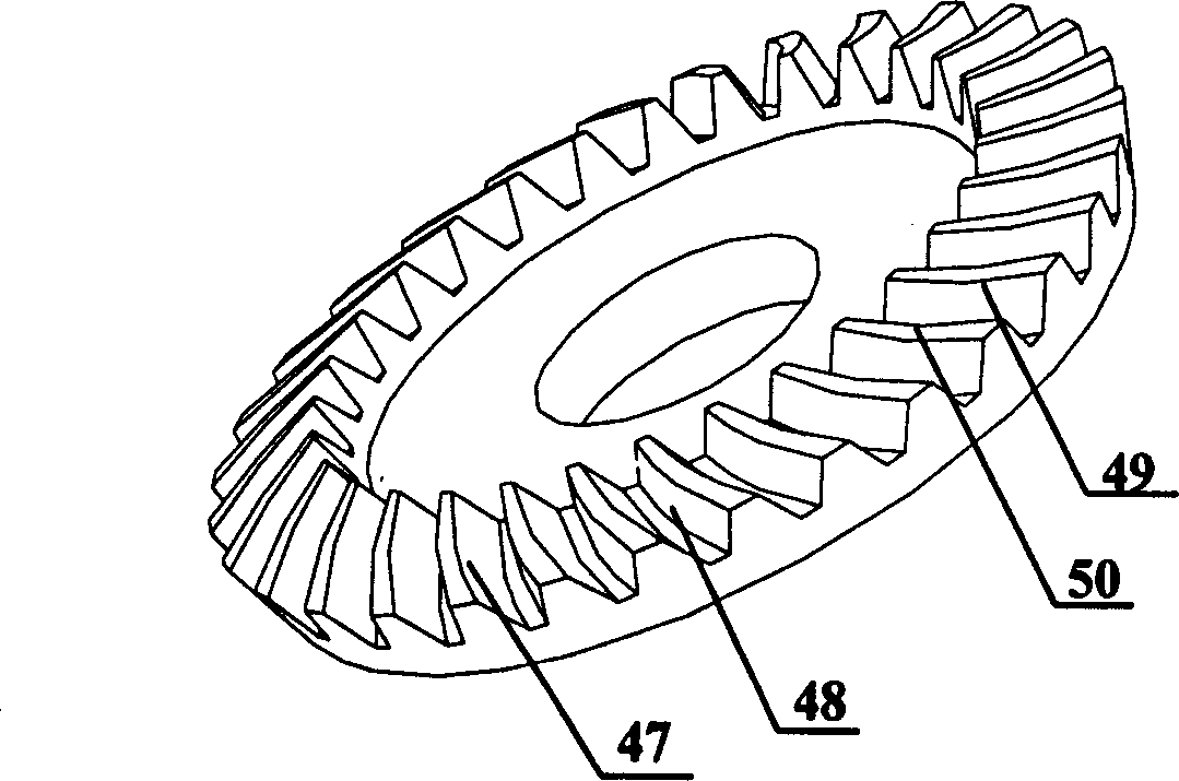
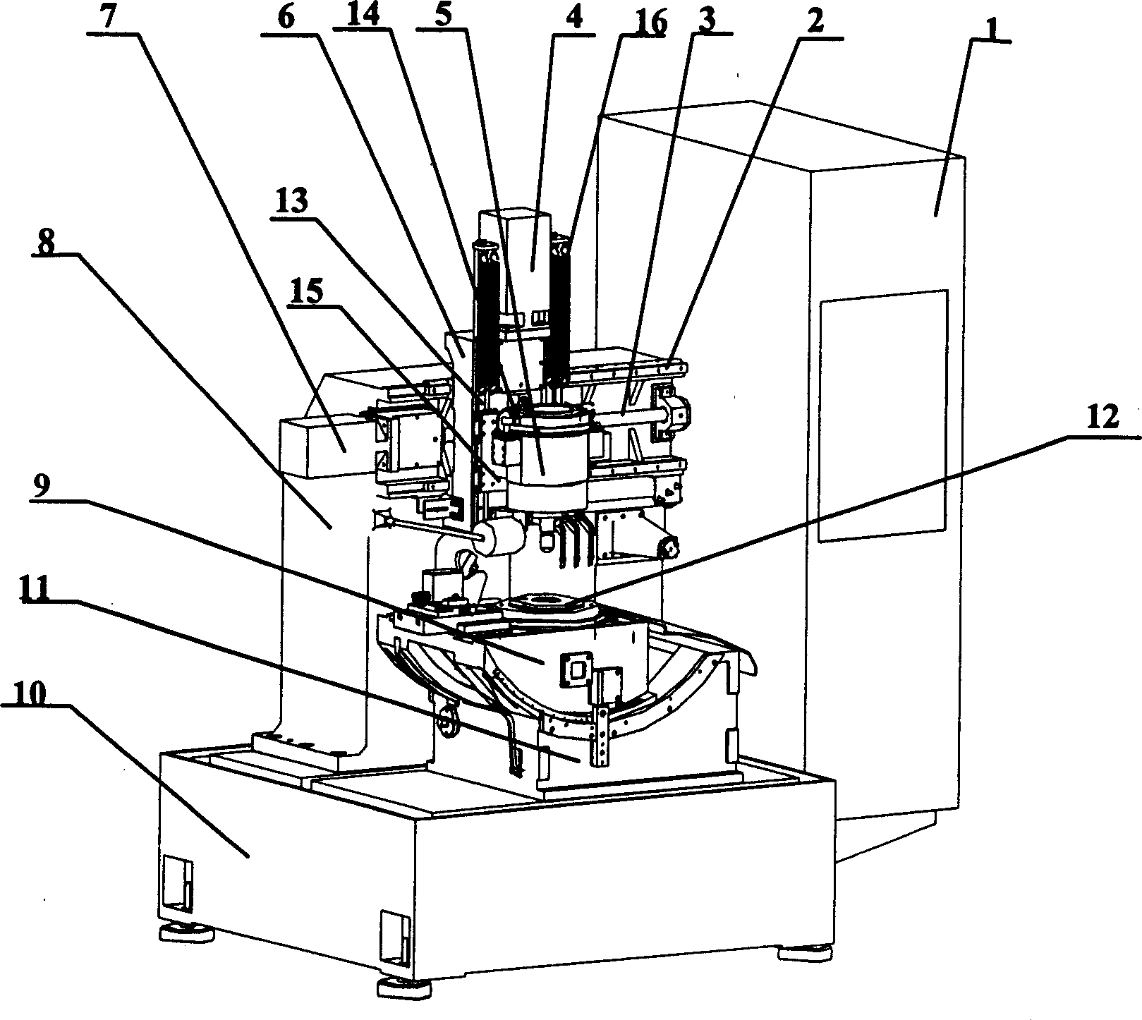
[0049] Such as figure 2 As shown, the CNC spiral bevel gear tip chamfering machine of the present invention includes: a body 10 and an electric control cabinet 1, a column 8 arranged on the body 10, and a column 8 arranged on the body 10 and located on the body 10. The front side of the turning table base 11 and the turning table 9 installed on the turning table base 11, the column 8 is provided with a horizontal moving mechanism and a vertical moving mechanism, and the vertical moving mechanism is set on the column 8 through the horizontal moving mechanism Above, the vertical moving mechanism is provided with a grinding head mechanism 5 for chamfering and grinding the spiral bevel gears, and a spindle for mounting the processed gear is provided at a position corresponding to the gri...


PUM


Abstract

The numerically controlled addendum chamfering machine for curve-tooth bevel gear includes a machine body, an electric control cabinet, uprights, a turnover stage and its pedestal, a horizontal shift mechanism and a vertical shift mechanism on the uprights, a chamfering mechanism on the vertical mechanism, and a main shaft for installing the machined gear. The present invention completes addendum chamfering of curve-tooth bevel gear by means of the three-shaft linkage of the two numerically controlled shafts on the uprights for linear motion and the numerically controlled rotating shaft on the stage. The machine has reasonable structure, reliable operation, high chamfering precision, high effect and high efficiency.

Description

technical field [0001] The invention relates to a gear processing machine tool. In particular, it relates to a numerical control spiral bevel gear addendum chamfering machine with accurate processing, high precision and high efficiency. Background technique [0002] The spiral bevel gear is the gear used for the main transmission of the car, which drives the wheel to rotate through the planetary mechanism. To make a spiral bevel gear, the first step is to make a blank, rough machining and finishing machining, and then heat treatment. After heat treatment, the edge of the gear is deformed, such as figure 1 As shown, the corners 50, 49 of the gear are deformed. Moreover, there are also processing errors in the processing of spiral bevel gears. If they are not processed and used directly for automobile assembly, the deformation of the edges will inevitably increase the noise when the automobile is running. [0003] In order to ensure that there is no error in the edge positi...

Claims


Application Information

Patent Timeline
IPC IPC(8): B23F19/12B23F23/02B23Q1/25B24B9/00
Inventor 柴宝莲胡光曦崔援朝
Owner TIANJIN NO 1 MACHINE TOOL WORKS
Why Eureka
Try Eureka