Anti-backflow method and device applied to heat dissipation equipment and heat dissipation system

A technology of backflow prevention device and heat dissipation device, which is applied to structural parts of electrical equipment, cooling/ventilation/heating modification, modification using gaseous coolant, etc. Guaranteed cooling effect

Active Publication Date: 2021-09-07
XIAN YIPU COMM TECH
View PDF25 Cites 0 Cited by
  • Summary
  • Abstract
  • Description
  • Claims
  • Application Information

AI Technical Summary

Problems solved by technology

[0005] The technical problem to be solved by the present invention is to provide an anti-reflux method and device, and a heat dissipation system in order to overcome the defects that the anti-reflux device has low compatibility with heat dissipation equipment and the setting is not flexible enough.

Method used


Image

  • Anti-backflow method and device applied to heat dissipation equipment and heat dissipation system
  • Anti-backflow method and device applied to heat dissipation equipment and heat dissipation system
  • Anti-backflow method and device applied to heat dissipation equipment and heat dissipation system

Examples


Embodiment 1

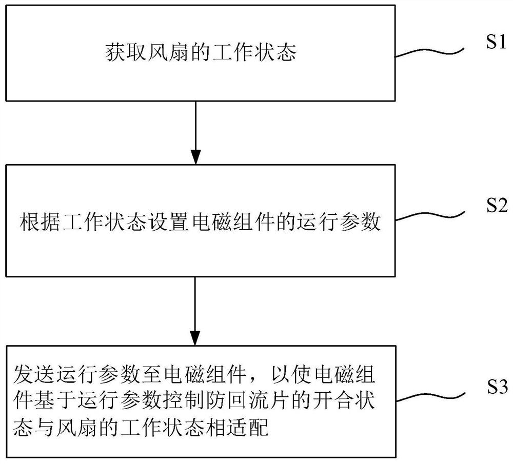
[0061] This embodiment provides a backflow prevention method applied to a heat dissipation device. The heat dissipation device includes at least two fans arranged side by side and anti-backflow sheets of magnetic materials arranged corresponding to the fans. seefigure 1 , the backflow prevention method includes the following steps:

[0062] S1. Obtain the working status of the fan;

[0063] S2. Set the operating parameters of the electromagnetic components according to the working state;

[0064] S3. Sending the operating parameters to the electromagnetic assembly, so that the electromagnetic assembly controls the opening and closing state of the anti-backflow sheet to match the working state of the fan based on the operating parameters.

[0065] In this embodiment, the heat dissipation device is specially set up for the heat dissipation of other main equipment with relatively large power and high calorific value, usually it may be a fan unit. The heat dissipation device may...

Embodiment 2

[0108] see Figure 4-6 , this embodiment also provides an anti-backflow device applied to heat dissipation equipment. The heat dissipation equipment includes at least two fans 1 arranged side by side and an anti-backflow sheet 2 of magnetic material corresponding to the fans 1. The anti-backflow device includes a controller and the electromagnetic assembly 3;

[0109] The electromagnetic assembly 3 is arranged on both sides of the air outlet of the fan; the controller is electrically connected to the electromagnetic assembly 3; the controller is used to implement the anti-backflow method in Embodiment 1, so as to control the electromagnetic assembly 3 to match the working state of the fan 1 .

[0110] in, Figure 4 is an overall side view of the heat sink and backflow preventer, Figure 5 for its front view, Figure 6 for its top view.

[0111] As a preferred embodiment, the fan 1 includes a PIN pin interface, and the controller is used to read the PIN pin interface to ob...

Embodiment 3

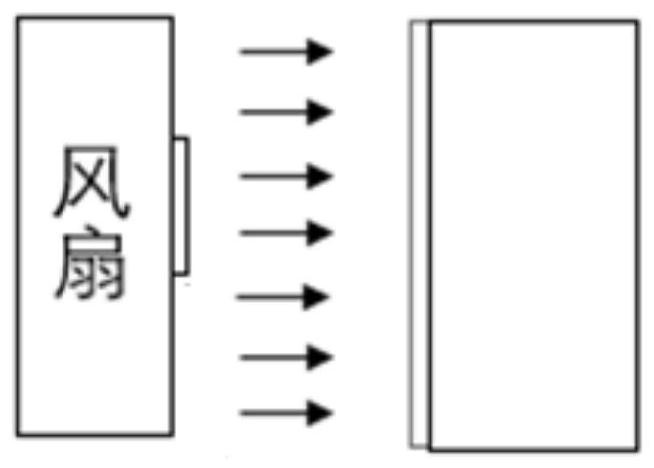
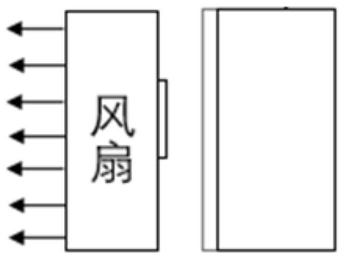
[0122] see Figure 7 , this embodiment also provides a heat dissipation system, including a heat dissipation device 4 and an anti-backflow device; the anti-backflow device also includes a connecting part 5 . A connection part 5 is provided at the central axis of the air supply port of each fan 1; electromagnetic assemblies 3 are respectively provided on both sides of the air supply port of each fan 1; When the return piece 2 is rotated by the connecting part 5 and rotated axially to the position parallel to the air outlet, it will be attached to the electromagnetic components 3 arranged on both sides of the fan 1 to close the air outlet. Please refer to Figure 8 . Of course, according to the installation position of the electromagnetic assembly 3, the anti-backflow sheet 2 can also be flipped in other ways or postures, as long as the air outlet of the fan 1 is closed to block the backflow gas.

[0123] The arrangement in this embodiment can better control the anti-backflow...


PUM


Abstract

The invention discloses an anti-backflow method and device applied to heat dissipation equipment and a heat dissipation system. The heat dissipation equipment comprises at least two fans arranged side by side and anti-backflow pieces made of a magnetic material and arranged corresponding to the fans. The anti-backflow method comprises the steps of: acquiring the working states of the fans; setting the operation parameters of an electromagnetic assembly according to the working states; and sending the operation parameters to the electromagnetic assembly, so as to enable the electromagnetic assembly to control the on-off states of the anti-backflow pieces to be matched with the working states of the fans based on the operation parameters. By controlling the electromagnetic assembly, the anti-backflow pieces adapt to various working states of the fans of the heat dissipation equipment, and normal air supply by the fans can be guaranteed no matter in a normal air blowing state or an air exhausting state. Meanwhile, once the fans fail in air blowing or air exhausting, it can be guaranteed that the anti-backflow pieces close the fans, airflow backflow is avoided, and the heat dissipation effect of the heat dissipation equipment is ensured.

Description

technical field [0001] The invention relates to the technical field of backflow prevention and heat dissipation, in particular to a backflow prevention method and device and a heat dissipation system applied to heat dissipation equipment. Background technique [0002] When heat dissipation equipment such as electric fan unit is working, multiple fans will work at the same time to ensure the heat dissipation effect. On the side of the air supply port of the fan, its working mode of performing air supply usually includes blowing and exhausting. [0003] When any one of the fans fails and stops, the remaining fans are still performing air supply normally. At this time, because the failed fan cannot generate thrust, the pressure at the air outlet is greater than the pressure at the air inlet, causing the airflow to flow from the failed fan. The air outlet returns to the air inlet. And such backflow of air flow will increase the wind resistance, so that the heat dissipation of t...

Claims


Application Information

Patent Timeline
Patent Type & Authority Applications(China)
IPC IPC(8): H05K7/20
CPCH05K7/20209H05K7/20145H05K7/2019Y02D10/00
Inventor 田颖曹凯
Owner XIAN YIPU COMM TECH
Why Eureka
Try Eureka