Shaft connecting structure of cooking device

A connection structure and cooking device technology, which is applied to special baking containers, household utensils, baking devices, etc., can solve the problem of poor heat dissipation effect of the shaft connection structure, failure of the rotation transmission of the clamp 5 and the movable cap 7, and the second Problems such as transmission shaft 52 wearing and tearing

Active Publication Date: 2021-09-10
罗泳志
View PDF2 Cites 0 Cited by
  • Summary
  • Abstract
  • Description
  • Claims
  • Application Information

AI Technical Summary

Problems solved by technology

[0002] For a cooker with a rotating grill, a shaft connection structure will be set between the shaft of the grill and the output shaft of the power take-off device, such as Figure 1 shows a shaft connection structure, including swinging bushing 4, The clamp 5 and the movable cap 7, the first transmission shaft 42 of the swing sleeve 4 is inserted into the lower end of the clamp 5, the movable cap 7 is sleeved on the second transmission shaft 52 at the upper end of the clamp 5, and they form a driving device The shaft connection structure between the output shaft 21 of 2 and the grill shaft transmits the power generated by the drive device 2 to the grill, so that the grill can also rotate, because the rotating shaft on the grill is directly plugged into the movable cap 7 And with the transmission, during the rotation process, the movable cap 7 drives the baking pan to rotate and needs to bear a relatively large torque. Since the movable cap 7 and the clip 5 are formed separately, the heat dissipation effect of this shaft connection structure is not good. , and after a long period of use, the movable cap 7 and the second transmission shaft 52 of the clip 5 will be worn, and even cause the rotation transmission between the clip 5 and the movable cap 7 to fail, so that the baking pan cannot be rotated in the driving device. Driven to rotate

Method used


Image

  • Shaft connecting structure of cooking device
  • Shaft connecting structure of cooking device
  • Shaft connecting structure of cooking device

Examples


Embodiment Construction

[0025] A shaft connection structure of a cooker according to the present invention will be described in conjunction with the accompanying drawings.

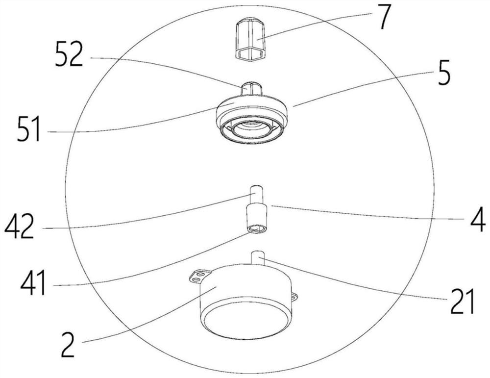
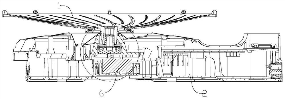
[0026] Such as Figure 2 to Figure 9 The cooker shown includes a base 2, a driving device 6, a rotating part 1 and a heating device (not shown in the figure), the driving device 6 is installed in the base 2, the rotating part 1 is a baking pan, and the baking pan is placed On the base 2, the driving device 6 is connected to the baking pan through a shaft connection structure, and drives the baking pan to rotate.

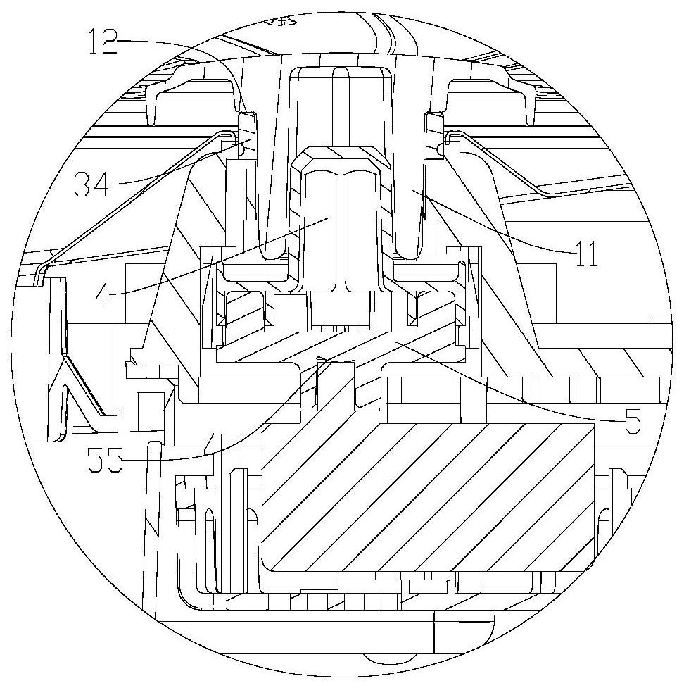
[0027] The driving device 6 has an output shaft 61, the rotating member 1 has an input shaft 11, and also includes an upper connection plate 4 and a lower connection plate 5, the upper connection plate 4 is integrated, and the upper connection plate 4 is integrally formed The process of processing and forming, also includes the process of processing and processing through welding and other fixed connections, and the up...


PUM


Abstract

The invention discloses a shaft connecting structure of a cooking device. The shaft connecting structure comprises a driving device, a rotating piece, an upper connecting disc and a lower connecting disc, the driving device is provided with an output shaft, the rotating piece is provided with an input shaft, and the upper connecting disc is integrated; the upper connecting disc comprises a first disc body and sleeves, a first transmission part is arranged on the upper surface of the first disc body and is in transmission connection with the input shaft, the sleeves are arranged at intervals, and the sleeves extend from the lower surface of the first disc body to the lower portion of the first disc body; the lower connecting disc comprises a second disc body and plug connectors, a second transmission part is arranged on the lower surface of the second disc body and is in transmission connection with the output shaft, the plug connectors are matched with the sleeves in number and position, and the plug connectors extend from the upper surface of the second disc body to the upper portion of the second disc body; and the plug connectors and the sleeves are mutually plugged, so that a heat dissipation cavity is formed between the first disc body and the second disc body. The shaft connecting structure of the cooking device is improved, and the situation that the transmission part, used for being connected with the rotating piece of the cooking device, of the shaft connecting structure is abraded too fast and consequently the transmission structure fails is avoided.

Description

technical field [0001] The invention relates to the field of cooking equipment, in particular to the shaft connection structure of the cooker. Background technique [0002] For a cooker with a rotating grill, a shaft connection structure is provided between the shaft of the grill and the output shaft of the power take-off device, such as figure 1 A shaft connection structure shown includes a swing sleeve 4, a clamp 5 and a movable cap 7, the first transmission shaft 42 of the swing sleeve 4 is inserted into the lower end of the clamp 5, and the movable cap 7 is sleeved on the clamp 5, on the second transmission shaft 52 at the upper end, they form the shaft connection structure between the output shaft 21 of the drive device 2 and the grill pan shaft, and transmit the power generated by the drive device 2 to the grill pan, so that the grill pan can also rotate, Since the rotating shaft on the baking pan is directly plugged with the movable cap 7 and cooperates with the tran...

Claims


Application Information

Patent Timeline
IPC IPC(8): A47J37/01A47J37/04
CPCA47J37/015A47J37/043
Inventor 罗泳志
Owner 罗泳志
Why Eureka
Try Eureka