Centrifugal separation cup and continuous separation method

A technology of centrifugal separation and centrifugal chamber, which is applied in the field of separation, can solve problems such as the difficulty of material particles, the lack of a method for continuous separation of material particles, and the destruction of the stability of the rotating fluid, so as to achieve optimized separation conditions, large centrifugal kinetic energy, and improved separation effect. Effect

Active Publication Date: 2020-04-07
广州穗阳生物学研究有限公司
View PDF7 Cites 0 Cited by
  • Summary
  • Abstract
  • Description
  • Claims
  • Application Information

AI Technical Summary

Problems solved by technology

However, it is difficult to apply it to the continuous separation of material particles in a heterogeneous system; because in the separation vessel, the turbulence phenomenon caused by the continuous entry and exit of liquid will destroy the stability of the rotating fluid in the separation system
[0004] Although a method combining membrane filtration and centrifugation has been proposed, there is no method for continuous separation of material particles

Method used


Image

  • Centrifugal separation cup and continuous separation method
  • Centrifugal separation cup and continuous separation method
  • Centrifugal separation cup and continuous separation method

Examples


example 1

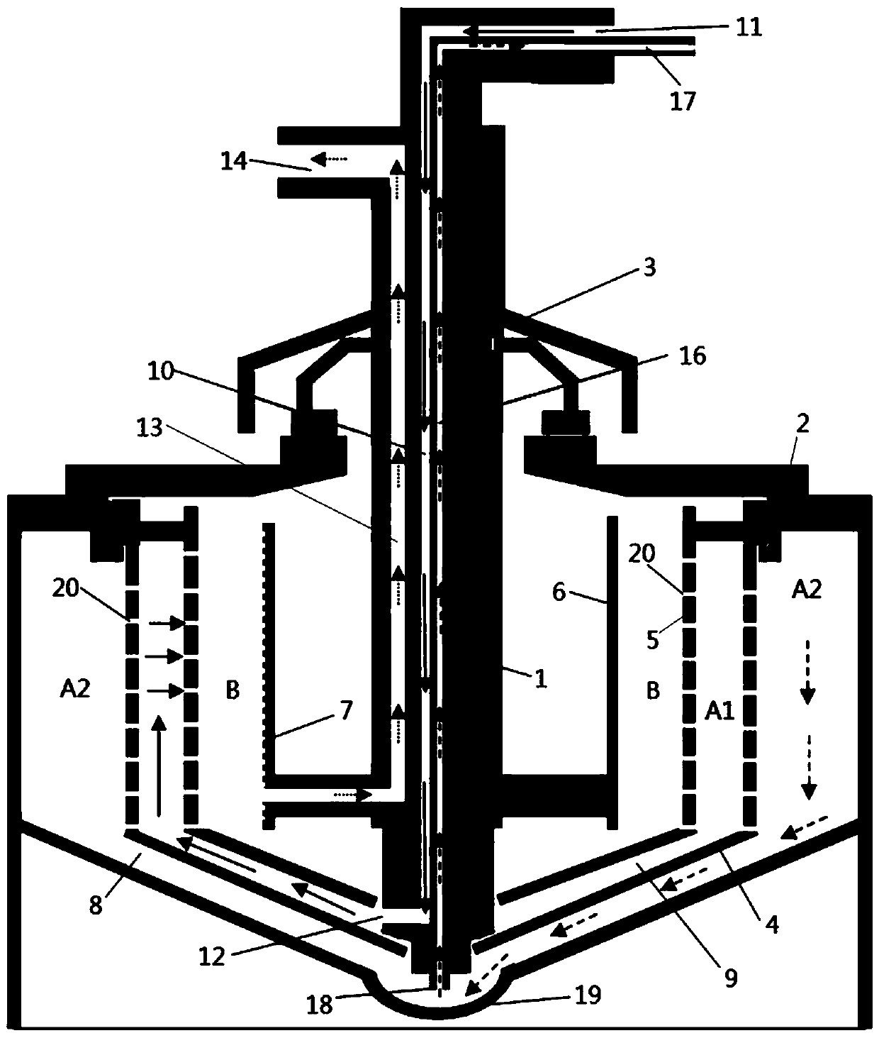
[0044] A centrifugal separation cup, comprising: a filter core tube, a centrifugal chamber, a fixed cover, a stabilizing sleeve and a flow guide sleeve.

[0045] The filter core tube is arranged inside the centrifuge cabin, the upper end is connected with the fixed cover, and the lower end is suspended in the cone bowl at the bottom of the centrifuge cabin. The filter core tube includes a filter bed and a core tube. A diversion groove is arranged on the filter bed, and a filter membrane is arranged outside the filter bed. The diversion grooves are collected into the filtrate inlet; the filtrate inlet is set at the lowest end of the filter bed.

[0046] The upper part of the centrifugal chamber is open, the middle part is cylindrical, the bottom is dish-shaped, and the center of the bottom is a bullet-shaped cone bowl; the bottom of the centrifugal chamber plays the role of gathering and separating the material particles. A stabilizing sleeve and a diversion sleeve are arrang...

example 2

[0060] In this example, a centrifuge cup is used for harvesting and washing cells during large-scale cell culture.

[0061] In this embodiment, the centrifuge cup is used to harvest and wash the cells, and a filter membrane with a pore size smaller than the cell diameter is used. The culture fluid line is connected to the liquid inlet, the waste liquid line is connected to the filtrate outlet, and the cells are harvested in the centrifuge chamber. After the liquid is fed in, switch the cleaning liquid pipeline to the liquid inlet for cell cleaning. After washing, the cells are collected through the concentrate outlet.

[0062] The pump provides positive pressure or / and negative pressure to form a pressure drop on both sides of the filter membrane as the driving force for the liquid flow in the centrifuge chamber. On the basis of considering the sensitivity of cells to centrifugal shear force, the relationship between centrifugal speed and filtration pressure was determined. ...

example 3

[0065] In this embodiment, a centrifuge cup is used for plasma separation.

[0066] Currently, the method of plasma collection is to use a centrifugal separation cup. In the existing separation cup structure, there is only a blood inlet and a plasma collection outlet, and there is no return path for blood cells. During the process of plasma collection, blood cells gradually gather in the separation cup, and the effective separation space of centrifugal separation is gradually occupied by cells, the separation effect becomes worse and worse, and finally loses the separation effect. At this time, the blood cells in the separation cup must be returned to After the infusion is emptied, the work of collecting plasma can be started again. Therefore, it collects plasma intermittently and does not have the function of continuous collection.

[0067] In this embodiment, a centrifuge cup is used for plasma separation. Connect the arterial line to the inlet, the venous line to the con...


PUM


Abstract

The invention relates to a centrifugal separation cup. The centrifugal separation cup comprises a filter element pipe, a centrifugal cabin, a fixed cover, a current stabilizing sleeve and a guide sleeve; the filter element pipe comprises a filter bed and a core pipe; the core pipe is fixedly mounted at the middle part of the filter bed; at least three independent runners are formed in the core pipe; the runners comprise a liquid inlet runner, a concentrated liquid runner and a filtered liquid runner; a filter membrane is arranged on the outer wall of the filter bed; the filter core pipe is arranged at the middle part of the centrifugal cabin; the fixed cover is connected to the core pipe of the filter core pipe, and is connected with the top of the centrifugal cabin; the lower part of thecurrent stabilizing sleeve sleeves the lower part of the core pipe, and the upper part of the current stabilizing sleeve sleeves the upper part of the centrifugal cabin; the guide sleeve is arranged between the current stabilizing sleeve and the centrifugal cabin; the guide sleeve is positioned at the bottom of the inner side of the centrifugal cabin; and the lower part of the guide sleeve sleevesthe lower part of the core pipe. The filter core pipe and the fixed cover are immovable in use; and the centrifugal cabin is rotated. The centrifugal separation cup can realize continuous separation.The invention further relates to a continuous separation method, and belongs to the technical field of separation.

Description

technical field [0001] The invention relates to the technical field of separation, in particular to a centrifugal separation cup and a continuous separation method. Background technique [0002] Centrifugation is to obtain the target product with different masses of material particles. Centrifugal separation technology is the centrifugal force generated by the rotation of the centrifuge. According to the difference in the sedimentation coefficient, mass, density and buoyancy of the material particles, the physical separation and analysis technology is separated and extracted by the centrifugal force field. It is widely used in biology, Medicine, agronomy, chemistry, chemical industry and other fields. [0003] When the heterogeneous system rotates around a central axis, the moving object will be subjected to centrifugal force. The higher the rotation rate, the greater the centrifugal force on the moving object. At the same rotational speed, substances of different sizes an...

Claims


Application Information

Patent Timeline
Patent Type & Authority Patents(China)
IPC IPC(8): B04B5/04
CPCB04B5/0407B04B5/0442B04B2005/0435B04B2005/045B04B2005/0464B04B2005/0471B04B2005/0478
Inventor 吴勤
Owner 广州穗阳生物学研究有限公司
Why Eureka
Try Eureka