Magnetic separation device

A technology of magnetic separation device and separation chamber, which is applied in magnetic separation, solid separation, chemical instruments and methods, etc., can solve the problems of high energy consumption and low separation efficiency, and achieve the effect of reducing energy consumption and saving costs

Active Publication Date: 2018-05-25
INST OF PROCESS ENG CHINESE ACAD OF SCI
View PDF4 Cites 2 Cited by
  • Summary
  • Abstract
  • Description
  • Claims
  • Application Information

AI Technical Summary

Problems solved by technology

However, most of the existing electromagnet separation equipment for magnetic particle catalysts have low separation efficiency, and the electromagnet needs to be switched on and off, which has the problem of high energy consumption.

Method used


Image

  • Magnetic separation device
  • Magnetic separation device
  • Magnetic separation device

Examples


Embodiment Construction

[0036] The technical solutions of the present invention will be further described below in conjunction with the accompanying drawings and through specific implementation methods.

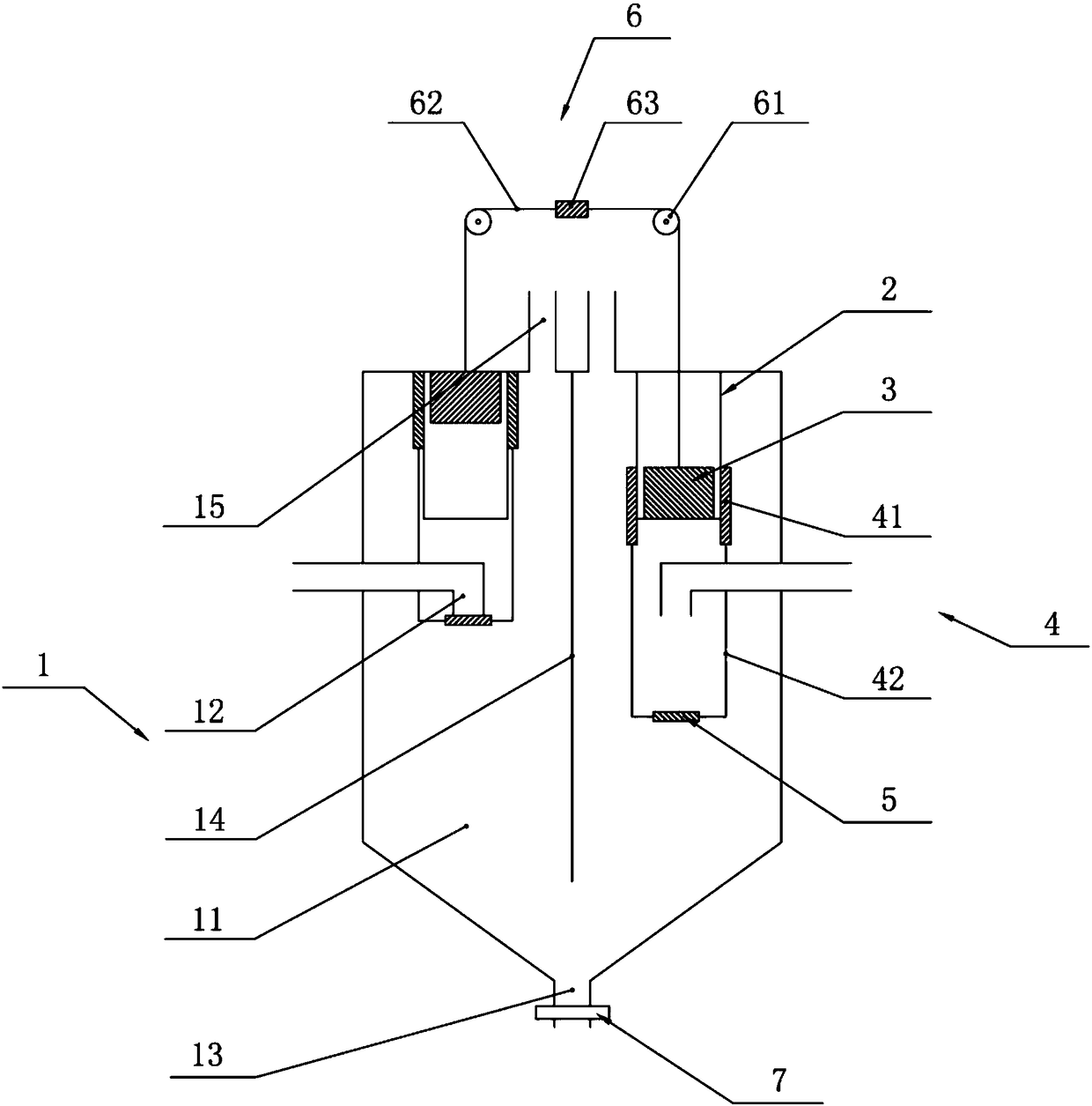
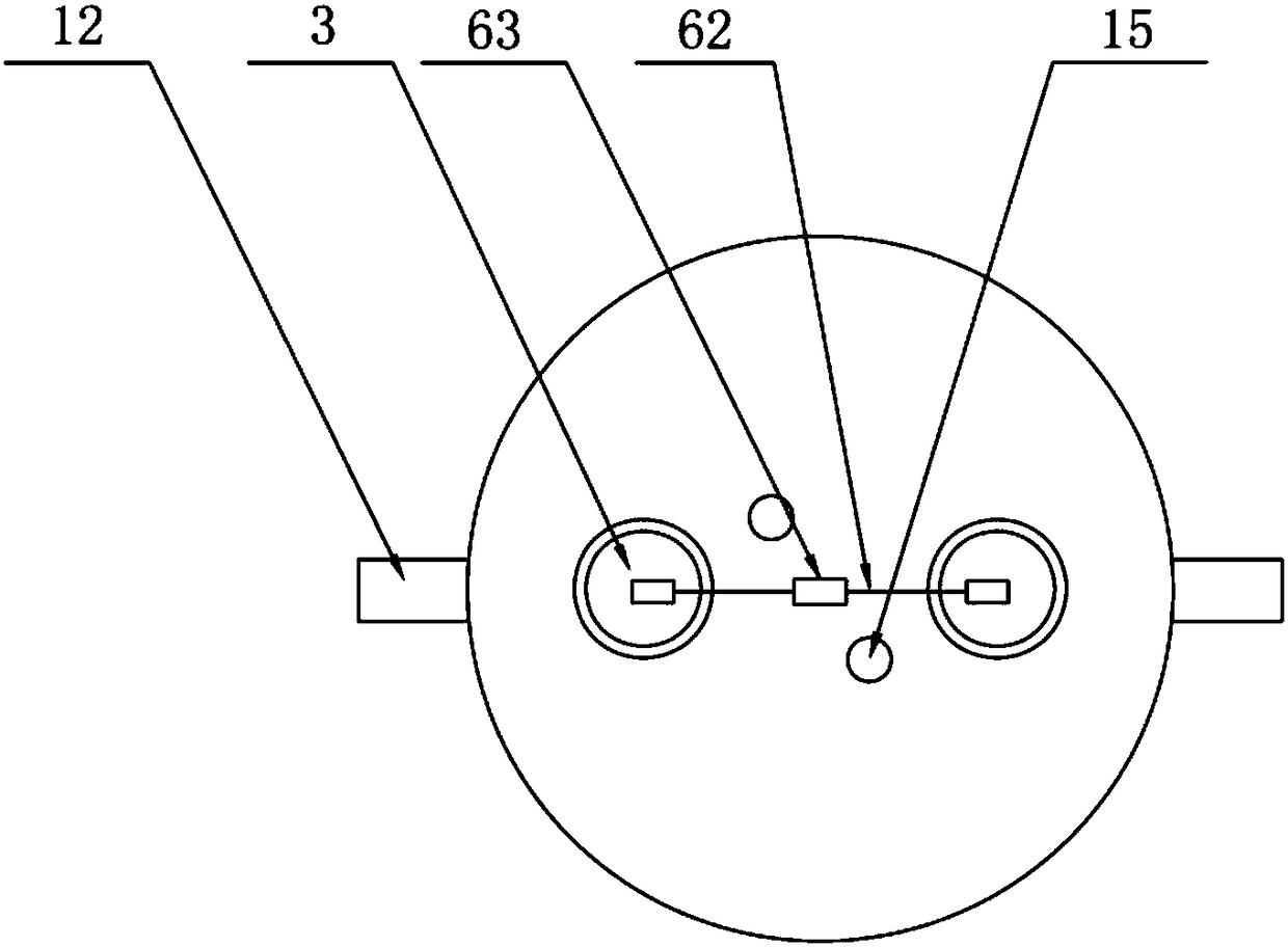
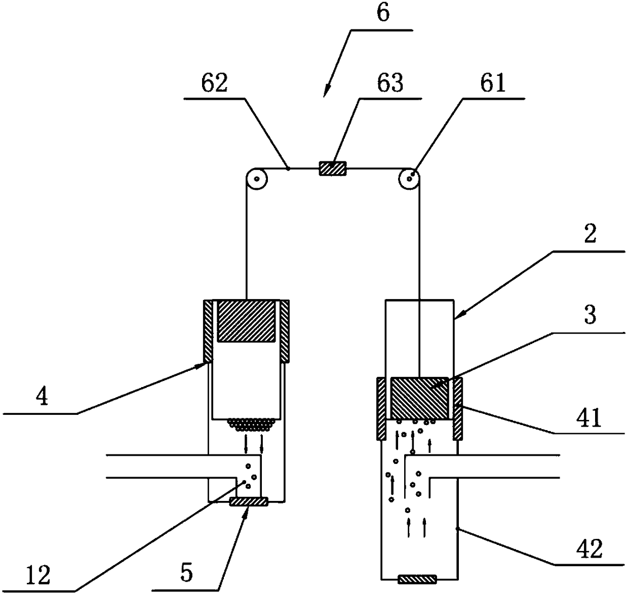
[0037] The invention provides a magnetic separation device, such as Figure 1-5 As shown, the magnetic separation device includes a separation chamber 1, a cylinder 2, a magnet 3, a bracket 4, a tray 5, a drive assembly 6 and a water seal assembly 7, wherein:

[0038] The above-mentioned separation chamber 1 has a cylindrical structure with an overall height of 3 meters, and its upper part is a cylindrical structure with a diameter of 2 meters. The bottom of the separation chamber 1 is a conical structure, and a dividing plate 14 with a length of 2.8 meters and a width of 2 meters is fixed in the middle of the separation chamber. One side of each separation chamber 11 is provided with a feed liquid inlet 12, specifically, the feed liquid inlet 12 is connected with an external pipeline, and the feed...


PUM


Abstract

The invention belongs to the technical field of catalyst particle separation and recovery and discloses a magnetic separation device. The magnetic separation device comprises a separation chamber, circular tubes and magnets, wherein the separation chamber is internally provided with two separation cavities, the separation cavities are provided with material liquid inlets and a magnetic particle recovery mouth, the circular tubes are arranged on the tops of the separation cavities in a sealed manner, and the magnets are located inside the corresponding circular tubes and capable of moving up and down in the axial direction of the corresponding circular tubes. According to the magnetic separation device, by means of the arrangements of the circular tubes inside the separation cavities and the magnets moving up and down inside the corresponding circular tubes, separation of magnetic particle catalyst can be realized, and by means of the arrangements of the two separation cavities, the continuous separation of the magnetic particle catalyst can be realized, and the separation efficiency is improved.

Description

technical field [0001] The invention relates to the technical field of separation and recovery of catalyst particles, in particular to a magnetic separation device. Background technique [0002] A catalyst is a substance that can change the chemical reaction rate of the reactants (increase or decrease) without changing the chemical balance during the chemical reaction, and its quality and chemical properties have not changed before and after the chemical reaction. Now it is widely used in the process of petrochemical, bioengineering and other fields. With the enhancement of environmental awareness and the continuous development of green chemistry, the development of environmentally friendly catalysts has attracted more and more attention from researchers. [0003] Although the addition of catalysts in industrial production greatly speeds up the reaction speed, expensive spent catalysts increase the cost of enterprises, so the recovery of catalyst particles has become an ine...

Claims


Application Information

Patent Timeline
Patent Type & Authority Applications(China)
IPC IPC(8): B03C1/12
CPCB03C1/12
Inventor 杨良嵘冯冬惠俊峰刘会洲安震涛
Owner INST OF PROCESS ENG CHINESE ACAD OF SCI
Why Eureka
Try Eureka