
Hydrate process and apparatus for separating gas mixture continuously
A technology of mixed gas and separation method, applied in separation method, carbon compound, dispersed particle separation, etc., can solve the problems of hydrate formation pressure reduction, system separation capacity reduction, low recovery rate, etc.
- Summary
- Abstract
- Description
- Claims
- Application Information
AI Technical Summary
Problems solved by technology
Method used
Image

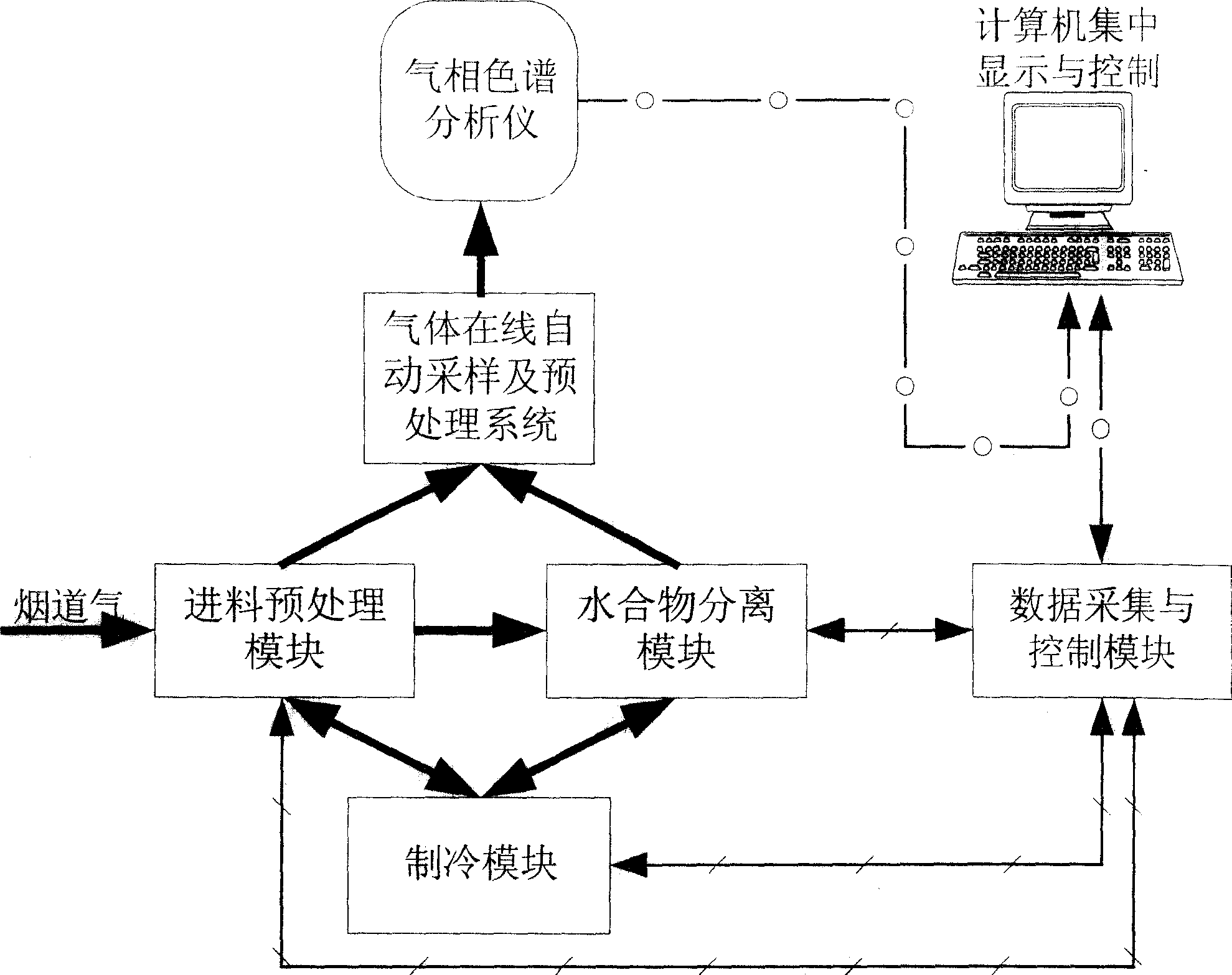
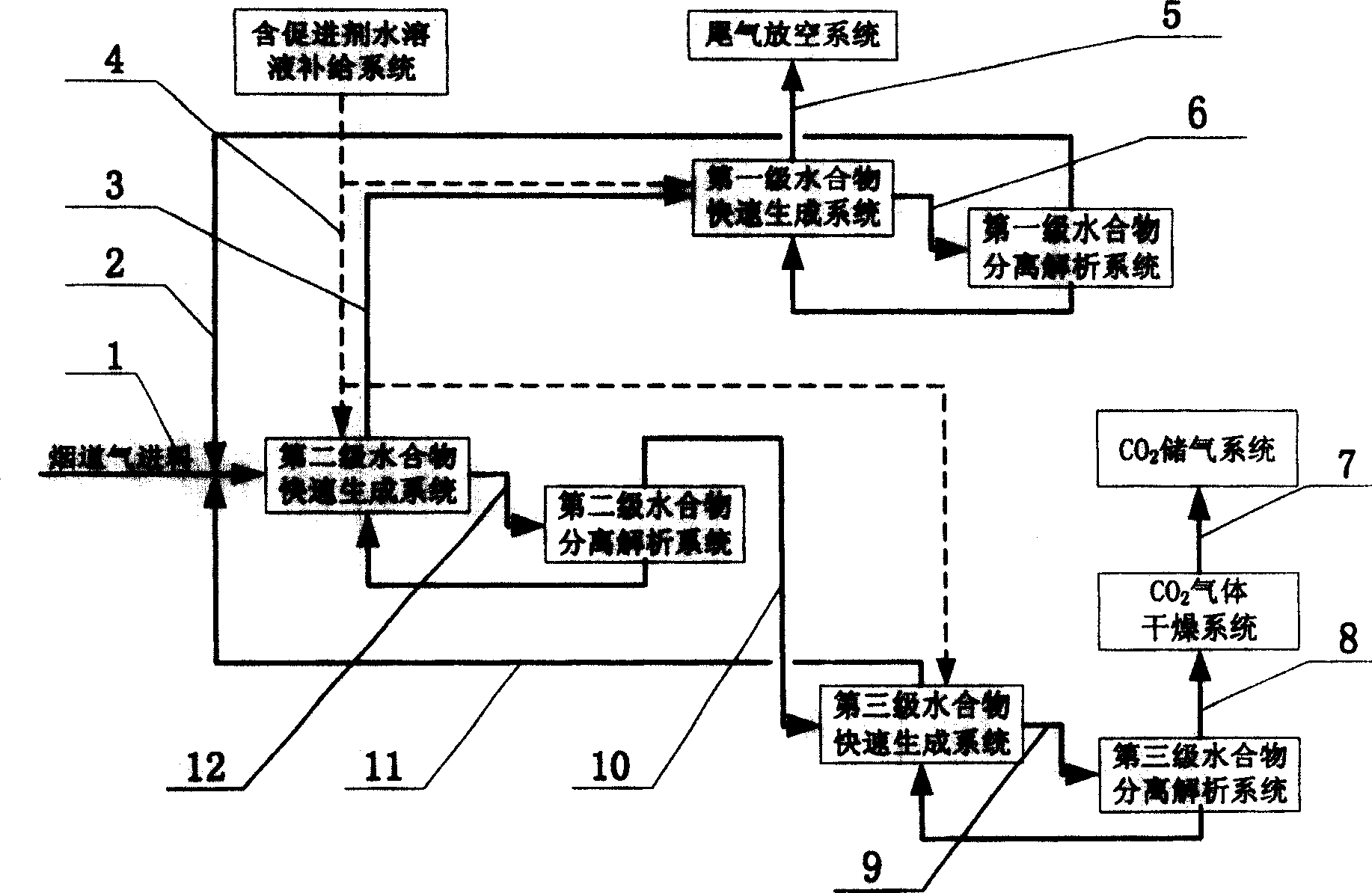
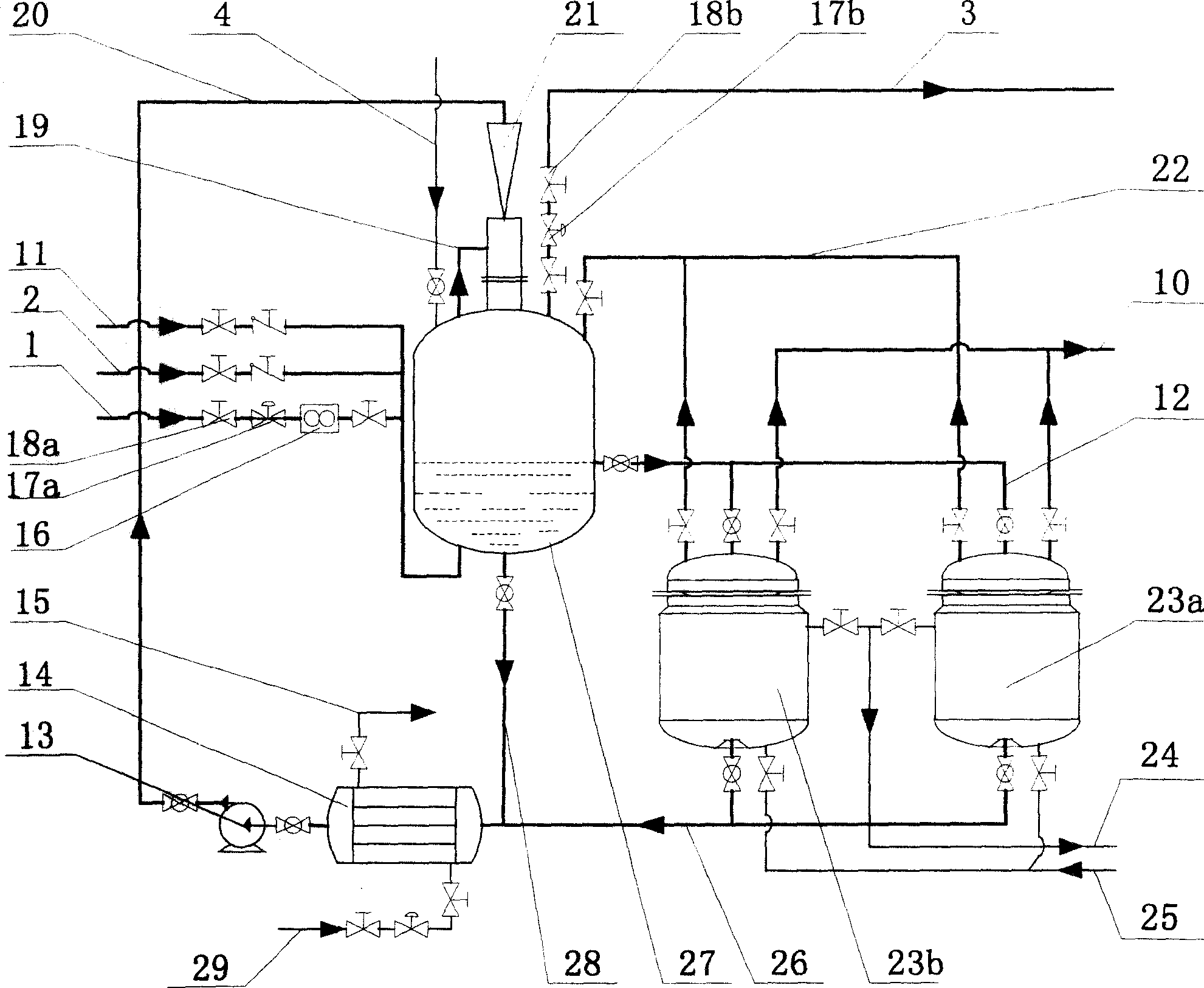
Examples
specific Embodiment approach
[0059] Such as figure 1 , 2, 3, after the flue gas is pretreated by water washing, drying, compression, pre-cooling, etc., the CO in the flue gas 2 The molar concentration is about 18%, the pressure is about 2.0MPa, and the temperature is 4°C. The pretreated flue gas enters the second-stage hydrate through the flue gas feed pipe 1, feed regulating valve 18a, and flow meter 16. The synthesis kettle 27; the aqueous solution containing 1.0% accelerator sodium lauryl sulfate is added to the first, second and third-stage hydrate synthesis kettles through the aqueous solution supply system and the aqueous solution supply pipeline 4; in the second-stage hydrate synthesis kettle 27 The aqueous solution containing the hydrate formation promoter is cooled to 2°C through the liquid phase circulation pipe 28 of the second-stage hydrate synthesis tank to the heat exchanger 14, and then enters the micro The bubble jet fully mixed reactor 21; the flue gas in the gas phase area at the top o...
PUM
 Abstract
Description
Claims
Application Information