
Rolling type insulated wire bending device

A technology of insulated wires and bending devices, which is applied in the field of bending machines, can solve problems such as time-consuming and labor-intensive, substandard bending angles, hidden dangers caused by safe and stable operation of transformers, etc.

Active Publication Date: 2021-09-10
国网浙江省电力有限公司江山市供电公司
View PDF9 Cites 0 Cited by
  • Summary
  • Abstract
  • Description
  • Claims
  • Application Information

AI Technical Summary

Problems solved by technology

The current bending operation of large-diameter insulated wires generally uses manual bending operations. Manual bending of large-diameter insulated wires is not only time-consuming and laborious, but also due to the limited arm strength of construction workers, the bending effect of large-diameter insulated wires is not good. It is easy to have the bending angle not up to the standard. After the large-diameter insulated wire is installed, it will cause stress on the terminal of the transformer. Long-term operation will lead to deformation of the terminal, etc., burying hidden dangers for the safe and stable operation of the transformer.

Method used


Image

  • Rolling type insulated wire bending device
  • Rolling type insulated wire bending device
  • Rolling type insulated wire bending device

Examples


specific Embodiment 1

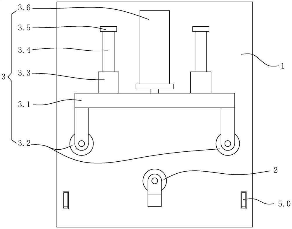
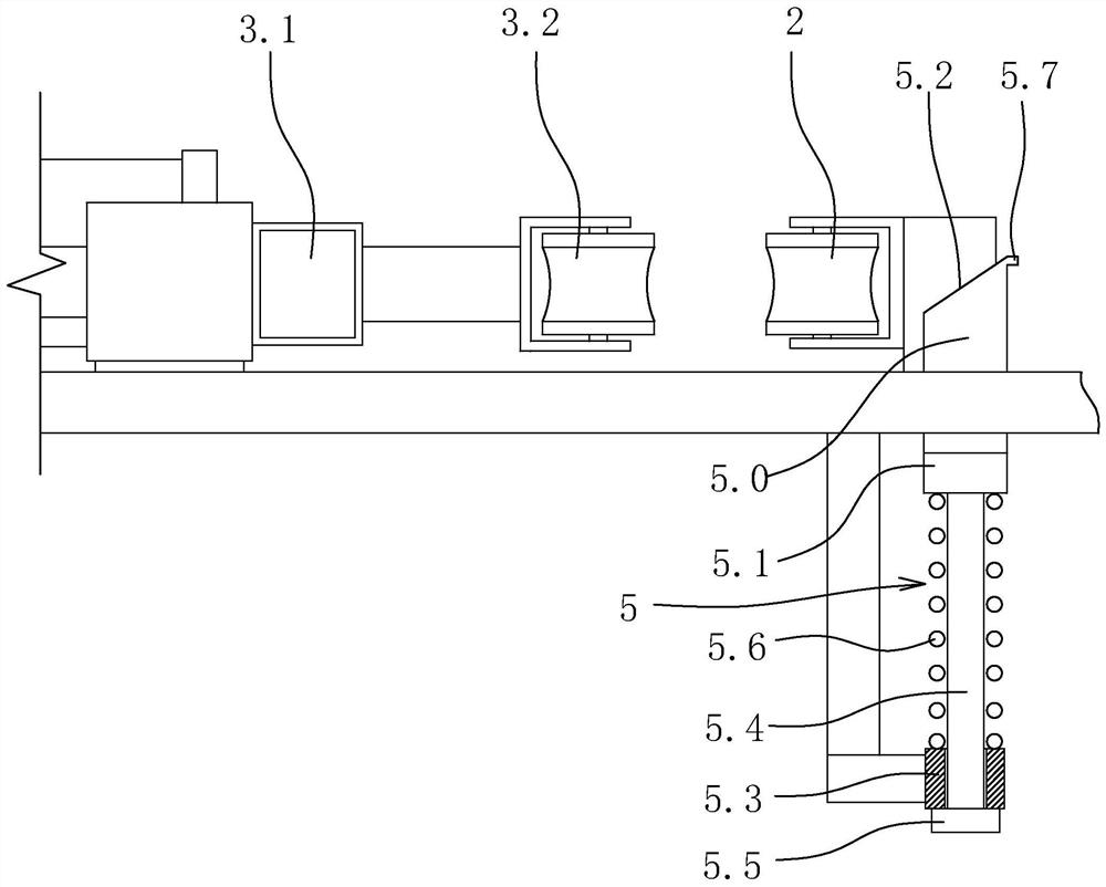
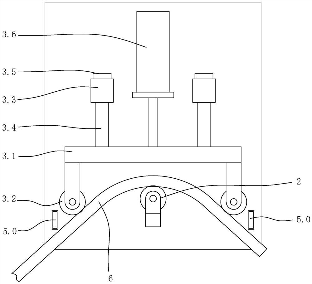
[0038] Specific embodiment one: as figure 1 As shown, a rolling type insulated wire bending device includes a frame, a fixed roller 2 and a wire bending mechanism 3 . The frame includes a workbench 1. In this embodiment, the workbench is distributed horizontally, and supporting feet are provided below the workbench. The fixed roller is arranged on the workbench, and the rotating shaft of the fixed roller is vertically distributed. The fixed roller is located above the workbench.

[0039] The wire bending mechanism 3 includes a translation support 3.1, a horizontal guide sleeve 3.3 fixed on the workbench, a horizontal guide rod 3.4 arranged on the translation support and slidingly matched with the horizontal guide sleeve, and a horizontal guide rod 3.4 arranged on the workbench for pushing the translation support. Jack 3.6 and two moving rollers 3.2 that are arranged side by side on the translation support. The rotating shaft of the moving roller is parallel to the rotating ...


PUM


Abstract

The invention discloses a rolling type insulated wire bending device, and aims to provide the rolling type insulated wire bending device which is convenient and rapid to operate, can ensure the bending effect of a large-diameter insulated wire and can bend the large-diameter insulated wire into a specific angle. The rolling type insulated wire bending device comprises a rack, a fixed roller and a wire bending mechanism, wherein the rack comprises a workbench; the fixed roller is arranged on the workbench, and a rotating shaft of the fixed roller is vertically distributed; the wire bending mechanism comprises a horizontal moving bracket, horizontal guide sleeves fixed on the workbench, horizontal guide rods which are arranged on the horizontal moving bracket and are in sliding fit with the horizontal guide sleeves, a jack which is arranged on the workbench and used for pushing the horizontal moving bracket and two movable rollers which are arranged on the horizontal moving bracket side by side; and rotating shafts of the movable rollers are parallel to the rotating shaft of the fixed roller, and the fixed roller is located between moving tracks of the two movable rollers.

Description

technical field [0001] The invention relates to a bending machine, in particular to a rolling type insulated wire bending device. Background technique [0002] In recent years, with the increase of social power consumption, the capacity of transformers has been continuously increasing, which makes the cross-sectional area of ​​insulated wires in the transformer area also increase. When the capacity of the transformer is 200kVA and above, according to the design requirements, the cross-sectional area of Large-diameter insulated wires of 300 mm2 and above; since the transformer low-voltage pile head is 3.8m high from the ground, and the working space at the high place is narrow, it is necessary to bend the large-diameter insulated wires into a specific angle and then install them. The current bending operation of large-diameter insulated wires generally uses manual bending operations. Manual bending of large-diameter insulated wires is not only time-consuming and laborious, bu...

Claims


Application Information

Patent Timeline
IPC IPC(8): B21F1/00
CPCB21F1/00
Inventor 毛云彪刘伟金良勇郑晓军徐冰周斌周剑云朱根深陈奕捷
Owner 国网浙江省电力有限公司江山市供电公司
Learn More