
Bending mechanism and bending method for wiring terminal of radio frequency coaxial connector

A terminal, radio frequency coaxial technology, applied in the field of assembly equipment, can solve the problems of inconsistent pin shape, inability to accurately locate the bent part, and inability to guarantee the effect of bending, and achieve the effect of ensuring the effect.

Inactive Publication Date: 2021-02-19
朱伟雅
View PDF1 Cites 0 Cited by
  • Summary
  • Abstract
  • Description
  • Claims
  • Application Information

AI Technical Summary

Problems solved by technology

[0005] 1. Before the pin is bent, it is impossible to accurately locate the part that needs to be bent, and the positioning position is remote or close, resulting in inconsistent shape of the pin after bending
[0006] 2. The effect of bending cannot be guaranteed by only one bending

Method used


Image

  • Bending mechanism and bending method for wiring terminal of radio frequency coaxial connector
  • Bending mechanism and bending method for wiring terminal of radio frequency coaxial connector
  • Bending mechanism and bending method for wiring terminal of radio frequency coaxial connector

Examples


Embodiment Construction

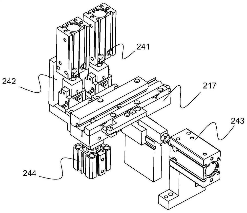
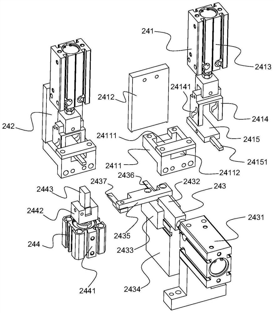
[0022]Such asfigure 1 As shown, a terminal bending mechanism of a radio frequency coaxial connector includes a frame and a material frame 217 installed on the frame, a first pre-compression component 241, a second pre-compression component 242, and side bending The component 243 and the bottom bending component 244; the material rack 217 is provided with a feeding channel; the material rack 217 is provided with a first bending station and a second bending station; the position of the first pre-compression component 241 is the same as that of the first bending The bending station is matched; the position of the second pre-compression component 242 matches the second bending station; the first pre-compression component 241 and the second pre-compression component 242 are located on the same side of the material rack 217; the side bending component 243 is installed On the other side of the material rack 217, the side bending component 243 is simultaneously matched with the first pre-co...


PUM


Abstract

The invention relates to the field of assembly equipment, in particular to a wiring terminal bending mechanism of a radio frequency coaxial connector. The bending mechanism comprises a rack, and a material frame, a first pre-pressing assembly, a second pre-pressing assembly, a side surface bending assembly and a bottom bending assembly which are arranged on the rack; a feeding channel is arrangedin the material frame; a first bending station and a second bending station are arranged on the material frame; the position of the first pre-pressing assembly is matched with that of the first bending station; the position of the second pre-pressing assembly is matched with that of the second bending station; the first pre-pressing assembly and the second pre-pressing assembly are located on thesame side of the material frame. The side face bending assembly is installed on the other side of the material frame and matched with the first pre-pressing assembly and the second pre-pressing assembly at the same time. The bottom bending assembly is installed below the material frame, and the position of the bottom bending assembly corresponds to the position of the second pre-pressing assembly.According to the pin bending device, the pin is transversely pressed firstly, then the pin is pressed again from bottom to top, and the bending effect is guaranteed by bending in different directionstwice in sequence.

Description

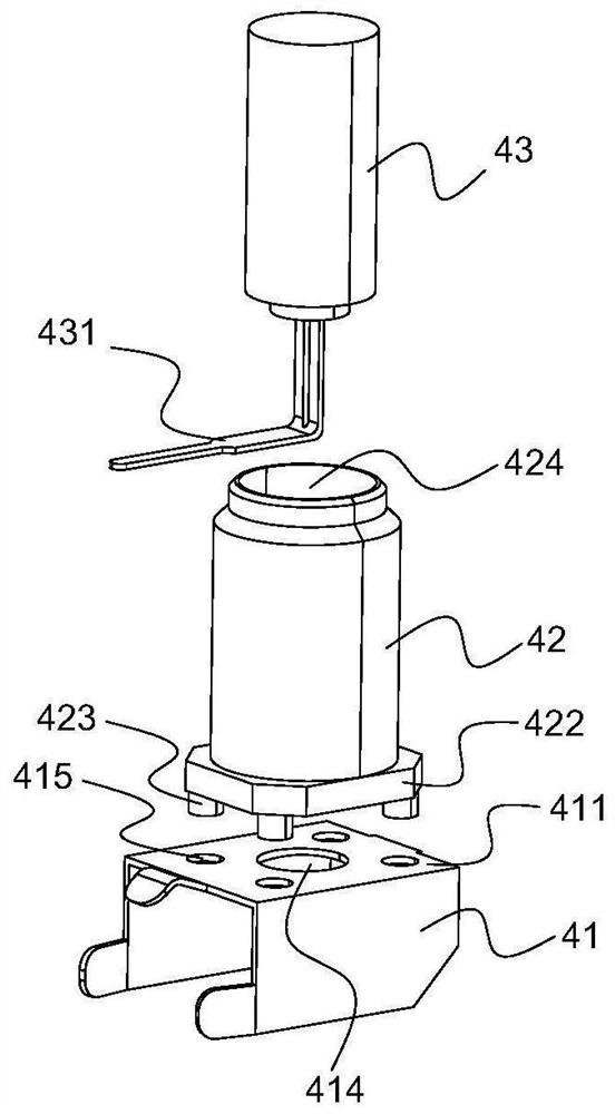
Technical field[0001]The invention relates to the field of assembly equipment, in particular to a terminal bending mechanism of a radio frequency coaxial connector.Background technique[0002]Radio frequency coaxial connector, referred to as RF connector. It belongs to a type of connector and is usually considered as a component attached to a cable or to an instrument. The radio frequency coaxial connector in this patent includes a base and a terminal; the base includes a base and a shell; the upper end of the base is a mounting surface, the center of the mounting surface is provided with a first through hole, and the mounting surface is also provided with a rectangular arrangement Four connecting holes; the shell is a hollow structure, the upper part of the shell is cylindrical, the shell is provided with a second through hole that penetrates up and down, and the second through hole communicates with the first through hole; the lower part of the shell is a connecting seat, The connec...

Claims


Application Information

Patent Timeline
Patent Type & Authority Applications(China)
IPC IPC(8): H01R43/16
CPCH01R43/16
Inventor 朱伟雅宋洪芝宋志强
Owner 朱伟雅
Learn More