
Medical multifunctional infusion seat

A multi-functional, drip technology, applied in the field of medical devices, can solve problems such as unfavorable physical recovery, not feeling very comfortable, and inability to adjust

Active Publication Date: 2021-09-14
THE AFFILIATED HOSPITAL OF QINGDAO UNIV
View PDF7 Cites 0 Cited by
  • Summary
  • Abstract
  • Description
  • Claims
  • Application Information

AI Technical Summary

Problems solved by technology

[0004] In order to overcome the disadvantages that the height of the existing infusion chairs is fixed and cannot be adjusted. For patients of different sizes, the general infusion time will be longer, and sitting on the infusion chair does not feel very comfortable, which is not conducive to physical recovery. , the technical problem to be solved is: to provide a kind of simple operation, reasonable and humanized design, the seat can be adjusted according to the individual to adapt to the infusion chair of the body, and the foot pedal and the bottle holder can be adjusted freely. chair

Method used


Image

  • Medical multifunctional infusion seat
  • Medical multifunctional infusion seat
  • Medical multifunctional infusion seat

Examples


Embodiment 1

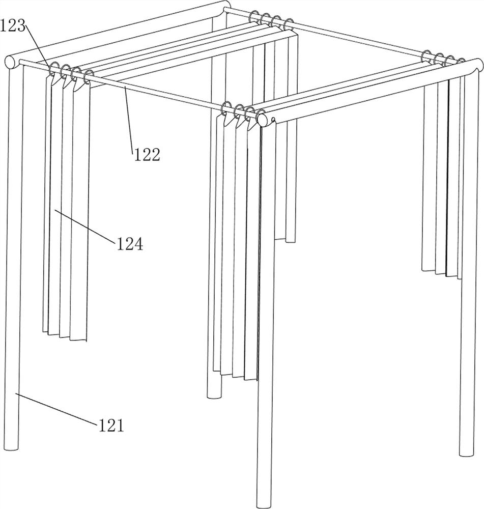
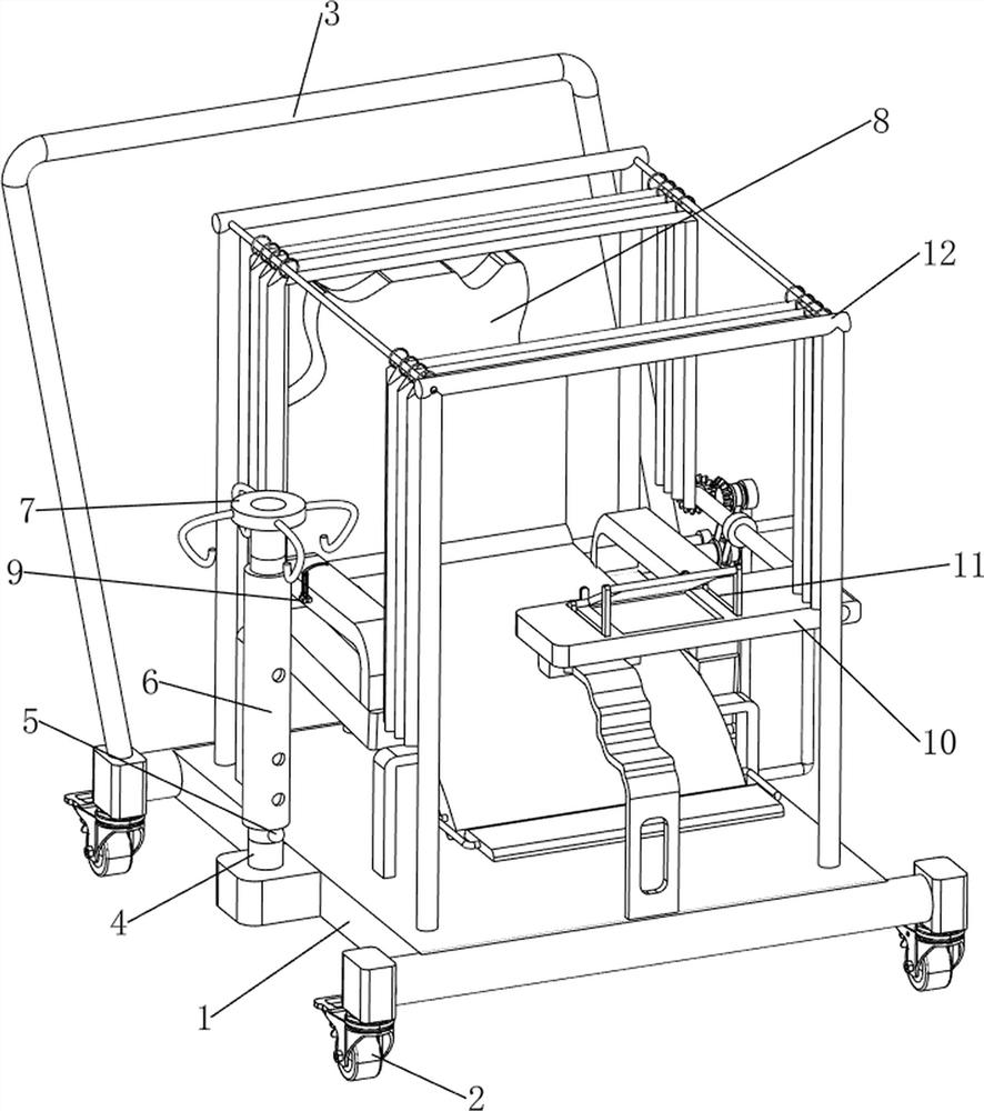
[0024] A kind of multi-functional drip drip seat for medical use, such as Figure 1-3 As shown, it includes a first support plate 1, a wheel 2, a push rod 3, a lifting rod 4, a buckle 5, an adjustment tube 6, a hook 7, a rotating mechanism 8 and a clamping mechanism 9. The wheel 2 is symmetrically rotated on both sides, the push rod 3 is provided on the top and rear side of the first support plate 1, the lifting rod 4 is provided on the left side of the top of the first support plate 1, and the buckle 5 is provided on the lower side of the front wall of the lifting rod 4 , the lifting rod 4 is slidably covered with an adjustment tube 6, the upper front wall opening of the adjustment tube 6 is matched with the buckle 5, the top of the lifting rod 4 is provided with a hook 7, the top of the first support plate 1 is provided with a rotation mechanism 8, and the rotation mechanism 8. A clamping mechanism 9 is provided on the left side of the middle part.

[0025] When a patient n...

Embodiment 2

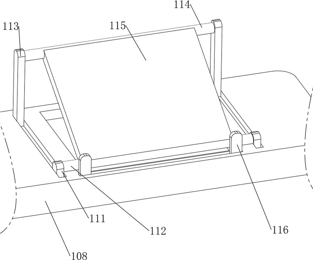
[0031] On the basis of Example 1, such as Figure 4-6 As shown, a table mechanism 10 is also included, and the table mechanism 10 includes a third supporting column 101, a fourth rotating shaft 102, a transmission assembly 103, a fourth supporting column 104, a fifth rotating shaft 105, a bevel gear 106, and a second supporting plate 107 and the first placement plate 108, the rear part of the right side wall of the first support plate 1 is provided with a third support column 101, and the upper side of the third support column 101 is provided with a fourth rotating shaft 102 in a rotating type, and the fourth rotating shaft 102 is connected to the second The transmission assembly 103 is connected between the right side of the rotating shaft 88, the rear part of the right side wall of the first support plate 1 is provided with a fourth support column 104, the fourth support column 104 is located in front of the third support column 101 in parallel, and the fourth support column ...


PUM


Abstract

The invention relates to the technical field of medical instruments, in particular to a medical multifunctional infusion seat. According to the medical multifunctional infusion chair, operation is easy, reasonable and humanized design is achieved, the chair can be adjusted according to individuals so as to adapt to the body, and a pedal and an infusion bottle rack can be freely adjusted. According to the technical scheme, the medical multifunctional infusion seat comprises a first supporting plate, wheels, a push rod, a lifting rod, a buckle and the like; and the wheels are rotationally and symmetrically arranged on the front side and the rear side of the bottom of the first supporting plate, the push rod is arranged on the rear side of the top of the first supporting plate, the lifting rod is arranged on the left side of the top of the first supporting plate, and the buckle is arranged on the lower side of the front wall of the lifting rod. By arranging a rotating mechanism, a backrest plate is pushed backwards, a handle on the right side is turned upwards along with a second rotating shaft to the angle comfortable for the left hand of a patient, and therefore the effect that the patient is in a comfortable infusion state can be achieved.

Description

technical field [0001] The invention relates to the technical field of medical devices, in particular to a medical multifunctional IV drip chair. Background technique [0002] It is inevitable that people will get sick. Some diseases need to be directly injected into the human body to exert their effects during treatment. Therefore, patients usually sit on a chair for infusion during the infusion process. Different patients sit back and forth on the infusion chair all day long. It will leave a lot of bacteria on the infusion chair, and the height of the existing infusion chairs is fixed and cannot be adjusted. For patients of different sizes, because the general infusion time will be longer, sitting on the infusion chair is not necessary. Feeling very comfortable, not conducive to physical recovery; this will cause great inconvenience to the patient. [0003] Therefore, we need to design an infusion chair with simple operation, reasonable humanized design, adjustable seat t...

Claims


Application Information

Patent Timeline
Patent Type & Authority Applications(China)
IPC IPC(8): A61M5/14
CPCA61M5/14
Inventor 张义文
Owner THE AFFILIATED HOSPITAL OF QINGDAO UNIV
Learn More