A high voltage gain dc-dc converter

A DC converter, DC-DC technology, applied in the direction of converting DC power input to DC power output, adjusting electrical variables, instruments, etc., can solve the problems of high converter gain, not high gain, large current stress, etc. gain, increasing static gain, reducing the effect of voltage stress

Active Publication Date: 2022-08-05
南京赛格米勒电气有限公司
View PDF0 Cites 0 Cited by
  • Summary
  • Abstract
  • Description
  • Claims
  • Application Information

AI Technical Summary

Problems solved by technology

However, low voltage conversion ratio, semiconductor high-voltage stress, and reverse recovery issues are fundamental issues for this converter in high-power applications.
Literature "A.Ajami, H.Ardi, and A.Farakhor, Anovel high step-up DC-DC converter based on integrating coupled inductor and switched-capacitor techniques for renewable energy applications, IEEE Trans.PowerElectron., vol.30, no .8, pp.4255–4263, Aug.2015." and "M. Eskandarpour Azizkandi, F. Sedaghati, and H. Shayeghi, An interleaved configuration of modified KYconverter with high conversion ratio for renewable energy applications; design, analysis and implementation, J.Oper.Autom.Power Eng., vol.7, no.1, pp.90–106, 2019.” proposed switched inductor (SL) and switched capacitor (SC) converters, which have high gain However, the circuit is complex and the current stress is large
Literature "X.Hu, J.Wang, L.Li, and Y.Li, Athree-winding coupled-inductor DC-DC converter topology with high voltage gain and reduced switch stress, IEEETrans.Power Electron., vol.33, no .2, pp.1453–1462, Feb.2018.” and literature “K.C.Tseng, J.T.Lin, and C.C.Huang, High step-up converter with three-winding coupler inductor for fuel cell energy source applications, EEE Trans.Power Electron. , vol.30, no.2, pp.574–581, Feb.2015.” proposed several high-boost DC-DC converters based on three-winding coupled inductors, the adjustment of voltage stress and voltage gain is more flexible, however Gain is not high enough

Method used


Image

  • A high voltage gain dc-dc converter
  • A high voltage gain dc-dc converter
  • A high voltage gain dc-dc converter

Examples


Embodiment Construction

[0033] The embodiments of the present invention will be described in further detail below with reference to the accompanying drawings.

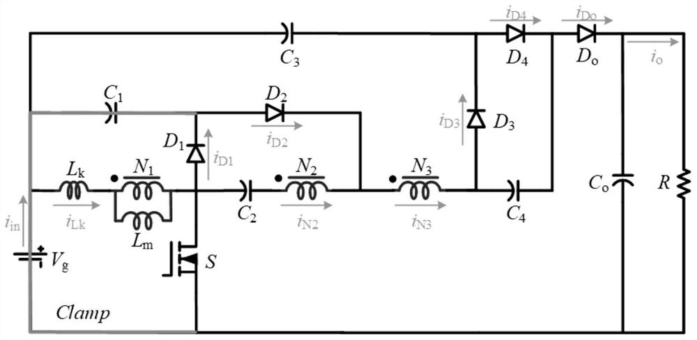
[0034] A high-voltage gain DC-DC converter, characterized in that the DC-DC converter includes a DC power supply, a power switch tube, a three-winding coupled inductor, a capacitor, and an output circuit;

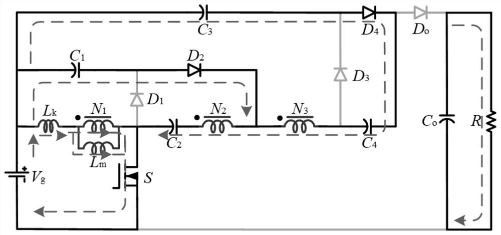
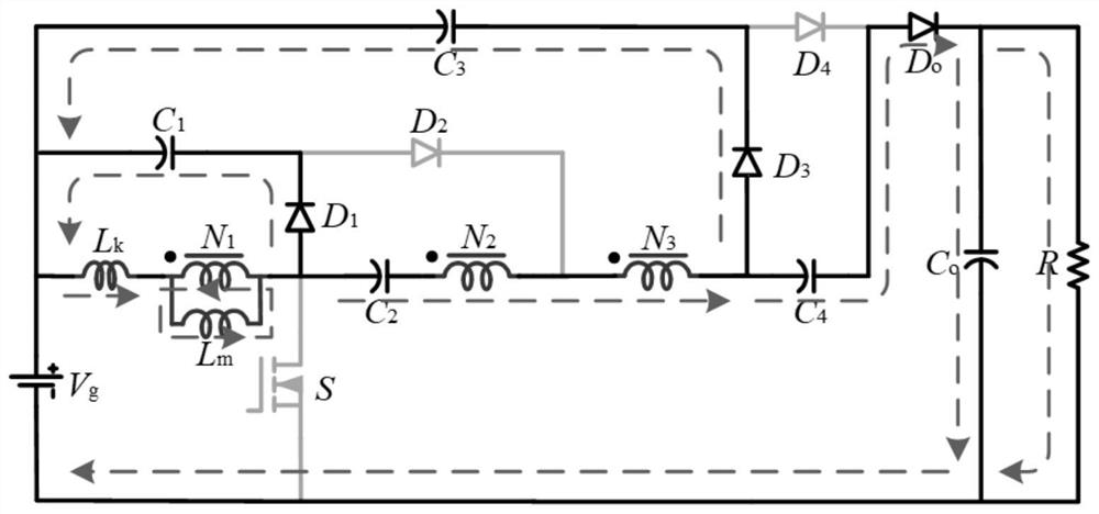
[0035] The on or off of the power switch tube is used to control the switching of the working state of the circuit, so as to control whether the DC power supply provides the energy required for the circuit operation to the coupled inductor and capacitor, and by changing the size of the duty cycle of the power switch tube and the coupling The turns ratio of the winding realizes the change of the input and output voltage gain, which is output by the output circuit.

[0036] Coupled inductors are used to replace a single independent energy storage inductor in the traditional boostable DC conversion circuit. Using the characteristics of simult...


PUM


Abstract

The invention discloses a high-voltage gain DC-DC converter, comprising a DC power supply, a power switch tube, a three-winding coupled inductance, a capacitor and an output circuit; it controls the on or off of the power switch tube to control the switching of the working state of the circuit, In this way, it is controlled whether the DC power supply provides the energy required for circuit operation to the coupled inductor and capacitor. By changing the duty cycle of the control power switch and the turns ratio of the coupled winding, the change of the input and output voltage gain is realized, which is output by the output circuit. The present invention realizes the boost conversion of the output voltage to the DC power supply voltage by changing the turns ratio of the three-winding coupled inductance, which can effectively avoid the situation of the limit duty cycle, and use a smaller duty cycle to achieve high output voltage. Conversion function; because the structure of the present invention can effectively reduce the voltage stress of the device in the circuit, reduce the loss, and improve the overall working efficiency of the circuit.

Description

technical field [0001] The invention belongs to the technical field of DC-DC conversion equipment, and in particular relates to a high-voltage gain DC-DC converter. Background technique [0002] At present, high-gain DC-DC boost converters are widely used in new energy fields, including photovoltaic systems, wind power generation, fuel cells, etc. However, the DC voltage level generated by resources such as photovoltaics and FCs is low, which is not suitable for grid integration. In view of the above mentioned problems, high boost DC-DC converters are required to increase the output DC voltage level of such resources. [0003] In recent years, various boost DC-DC converters with boost technology have been proposed. Isolation converters utilize transformers with large turns ratios, which have higher voltage conversion ratios. However, an excessively large turns ratio will lead to excessive leakage inductance, thereby reducing converter efficiency and increasing switching v...

Claims


Application Information

Patent Timeline
Patent Type & Authority Patents(China)
IPC IPC(8): H02M3/156
CPCH02M3/156
Inventor 丁新平
Owner 南京赛格米勒电气有限公司
Why Eureka
Try Eureka