Voltage conversion device

A technology of voltage conversion and reactor

Pending Publication Date: 2022-07-29
TOYOTA JIDOSHA KK
View PDF2 Cites 0 Cited by
  • Summary
  • Abstract
  • Description
  • Claims
  • Application Information

AI Technical Summary

Problems solved by technology

In the technique of this Patent Document 1, if the same upper limit value of the command effective time is set for individuals whose execution effective time is shortened, there is a possibility that a sufficient effective time cannot be obtained and the expected voltage conversion ratio cannot be obtained.

Method used


Image

  • Voltage conversion device
  • Voltage conversion device
  • Voltage conversion device

Examples


example 1

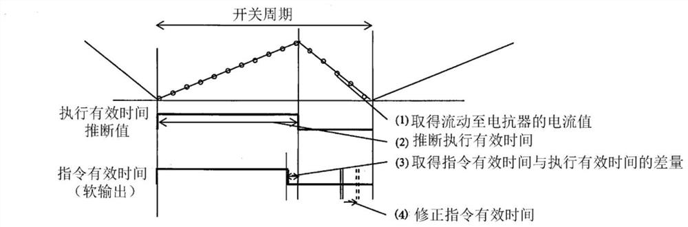
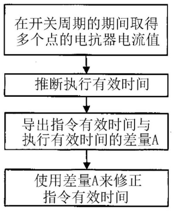
[0055] (Example 1): The control unit may sample the reactor current value at multiple points during the effective time of the switching cycle, and estimate the effective time length of execution from the difference A between the minimum value and the maximum value of the reactor current value during the effective time . However, in this case, it is sufficient to sample at least two points of the reactor current value during the effective time of the switching cycle.

example 2

[0056](Example 2): The control unit may use the slope of the reactor current in the effective time obtained by sampling the reactor current value at multiple points during the effective time and the ineffective time of the switching cycle and the difference between the reactor current in the ineffective time The intersection of the slopes is used to infer the effective length of time to execute. In this case, the reactor current value may be sampled at least 2 points during the valid time of the switching cycle, and the reactor current value may be sampled at least 2 points during the invalid time of the switching cycle.

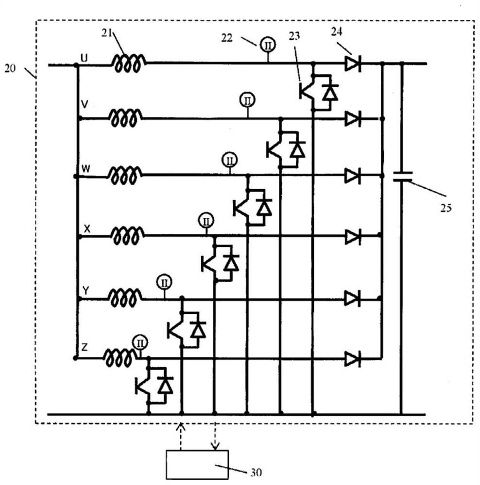
[0057] When the converter is a magnetically coupled converter, the effective execution time length can be estimated in each circuit by the method of (Example 1) or (Example 2) described above.

[0058] In the present disclosure, a reactor having a core around which one independent coil is wound is referred to as a non-magnetically coupled reactor. In the pr...


PUM


Abstract

The invention provides a voltage conversion device capable of suppressing individual variation of a voltage conversion ratio and realizing a high voltage conversion ratio. A voltage conversion device is provided with a reactor, a switching element, a diode, a current sensor, and a control unit that detects a current value of the reactor multiple times during a switching period, and that calculates an estimated execution effective time length on the basis of a change in the current value of the reactor detected during the switching period. The control unit calculates a difference between the estimated execution valid time length and a command valid time length instructed by the control unit. The control unit uses the difference amount to correct the command valid time length when the ON command is performed at any time after the next time within a range in which a predetermined command valid time upper limit value is not exceeded.

Description

technical field [0001] The present disclosure relates to voltage conversion devices. Background technique [0002] Various studies have been conducted on converters included in systems used in vehicles such as fuel cell vehicles. Circuits including reactors, switching elements, diodes, capacitors, and the like are often used in DC / DC converters used in various electronic devices and the like. The increase and decrease of the current flowing to the reactor are controlled by the on / off signal of the switch. [0003] For example, Patent Document 1 discloses a technique based on a reactor flowing to a DC / DC converter in order to provide a DC / DC converter capable of maintaining the protective function of the circuit against excessive current even if the current detection circuit has a defect The upper limit of the duty ratio (command valid time) of the switch is set by delaying the time when the current is detected, and the switch is controlled so as not to exceed the upper lim...

Claims


Application Information

Patent Timeline
Patent Type & Authority Applications(China)
IPC IPC(8): H02M3/156H02M3/158
CPCH02M3/156H02M3/1584H02M1/0009H02M1/0025H02M3/158
Inventor 梅原孝宏
Owner TOYOTA JIDOSHA KK
Why Eureka
Try Eureka