Supercharge Your Innovation With Domain-Expert AI Agents!

Scroll compressor

A technology of scroll compressors and scroll parts, which is applied in the field of scroll compressors, and can solve the problems of size limitation, inability to swing large scroll parts, etc.

Active Publication Date: 2021-09-14
MITSUBISHI ELECTRIC CORP
View PDF7 Cites 0 Cited by
  • Summary
  • Abstract
  • Description
  • Claims
  • Application Information

AI Technical Summary

Problems solved by technology

[0004] However, in the scroll compressor of Patent Document 1, it is necessary to avoid interference between the positioning pins connecting the fixed scroll and the frame with the oscillating scroll, so that the oscillating scroll cannot be The size of the scroll is made larger
Therefore, in the scroll compressor of Patent Document 1, the size of the scroll capacity that determines the upper limit capacity of the compressor is limited.

Method used


Image

  • Scroll compressor
  • Scroll compressor
  • Scroll compressor

Examples


Embodiment approach 1

[0020] [Structure of Scroll Compressor 100]

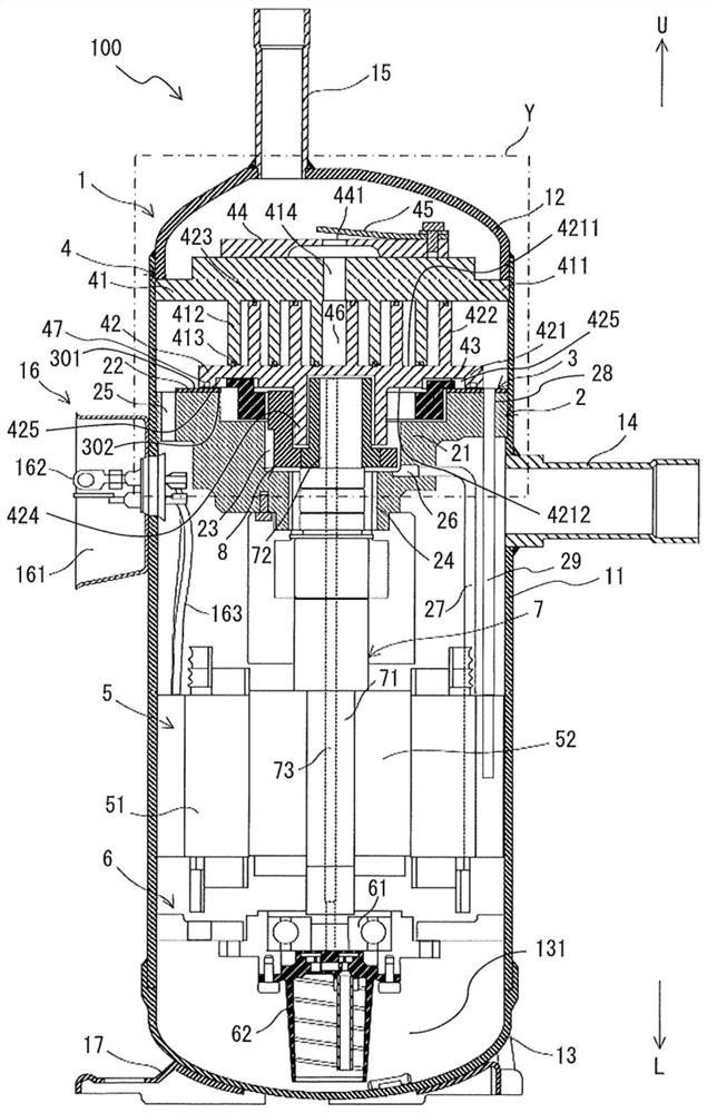
[0021] figure 1 It is a vertical cross-sectional view of scroll compressor 100 according to Embodiment 1 of the present invention. The scroll compressor 100 is applied, for example, to a refrigeration cycle device used for refrigeration or air conditioning, such as a refrigerator or a freezer, a vending machine, an air conditioner, a refrigeration device, and a water heater. The scroll compressor 100 sucks in the refrigerant circulating in the refrigeration circuit of the refrigeration cycle device, compresses it into a high-temperature and high-pressure state, and discharges it.

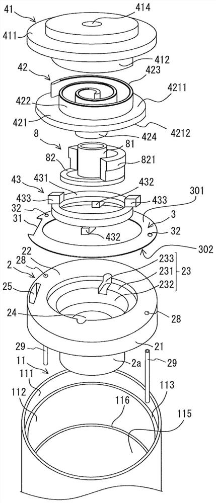
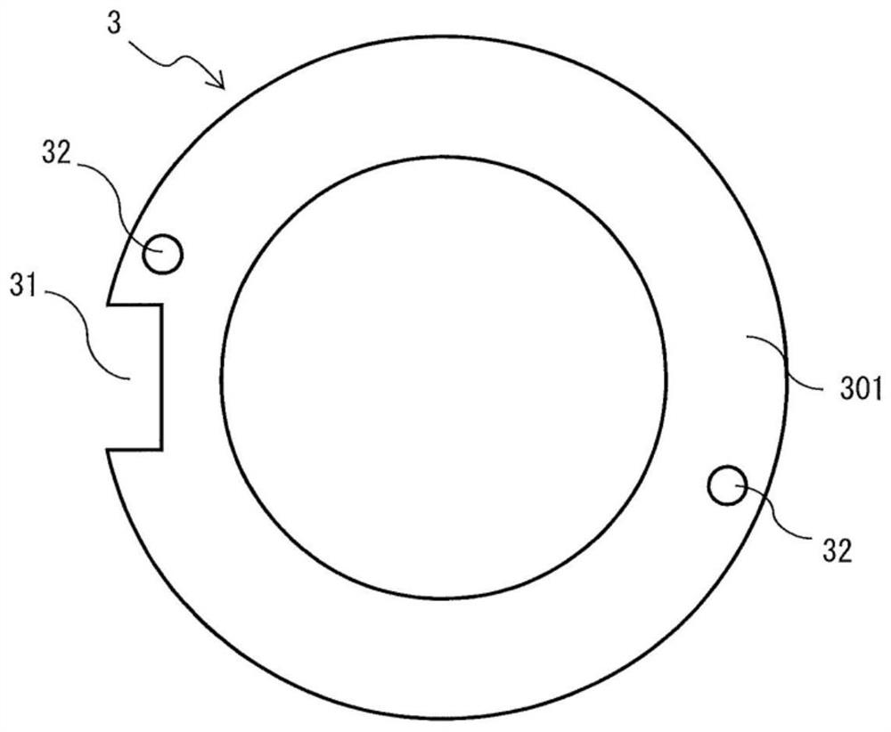
[0022] The scroll compressor 100 includes a casing 1 , a main frame 2 , a thrust plate 3 , a compression mechanism 4 , and a thrust oil return pipe 29 . In addition, the scroll compressor 100 includes a drive mechanism portion 5 , a subframe 6 , a crankshaft 7 , and a bush 8 . The scroll compressor 100 according to Embodiment 1 is used in a state wher...

Embodiment approach 2

[0108] Figure 9 It is a bottom view of the orbiting scroll 42a used in the scroll compressor 100 according to Embodiment 2 of the present invention. pair with Figure 1 to Figure 6 The parts having the same structure as those of the scroll compressor 100 are denoted by the same reference numerals, and description thereof will be omitted. In addition, items not particularly described in the swing scroll 42a are the same as those of the swing scroll 42 of the scroll compressor 100 according to Embodiment 1 of the present invention, and the same functions and structures are assigned the same reference numerals. describe.

[0109] The swing scroll 42 a is different from the swing scroll 42 of the scroll compressor 100 according to Embodiment 1 in that the oil supply groove 47 communicates with the second Oldham groove 425 . That is, the second crosshead groove 425 is formed to communicate with the oil supply groove 47 . Therefore, in the scroll compressor 100 , the lubricatin...

Embodiment approach 3

[0112] Figure 10 It is a longitudinal sectional view of the seal 49a used in the scroll compressor 100 according to Embodiment 3 of the present invention. pair with Figure 1 to Figure 6 as well as Figure 9 The parts having the same structure as those of the scroll compressor 100 are denoted by the same reference numerals, and description thereof will be omitted. In addition, items not particularly described in the seal 49a are the same as the seal 49 of the scroll compressor 100 according to Embodiment 1 of the present invention, and the same functions and structures are described using the same reference numerals.

[0113] The seal 49 a is different from the seal 49 of the scroll compressor 100 according to Embodiment 1 in that the through hole 491 is formed in the seal 49 a. The number of through-holes 491 formed in the sealing material 49a may be one or plural. The through hole 491 is formed in the radial direction of the second platen 421 in a state where the packin...


PUM


Abstract

A scroll compressor (100) comprises: a shell (1) that constitutes an outer shell and forms an oil sump (131) that stores lubricating oil inside; a fixed scroll (41) housed in the shell; an orbiting scroll (42) housed in the shell and forming together with the fixed scroll a compression chamber; a frame (2) holding the orbiting scroll; a thrust plate (3) disposed between the orbiting scroll and the frame; and a thrust oil return pipe (29) which is fixed to the frame and through which lubricating oil returning to the oil sump flows, wherein a hole (32) passing through between a first surface portion that is in sliding contact with the orbiting scroll and a second surface portion facing the frame is formed in the thrust plate, the thrust oil return pipe is inserted into the hole and fitted with the thrust plate, and the upper end of the thrust oil return pipe does not protrude from the first surface portion of the thrust plate.

Description

technical field [0001] The present invention relates to a scroll compressor used in refrigeration cycles such as refrigeration or air conditioning applications. Background technique [0002] A conventional scroll compressor includes: a frame that holds an oscillating scroll so that the oscillating scroll can slide; a fixed scroll that forms a compression chamber together with the oscillating scroll; and a housing that accommodates the frame and A fixed scroll (for example, refer to Patent Document 1). In the scroll compressor of Patent Document 1, a space is formed in each of the fixed scroll and the frame, a positioning pin is inserted into the space, and the frame and the fixed scroll are connected by the positioning pin. In the scroll compressor of Patent Document 1, when the thrust plate is disposed between the frame and the orbiting scroll, it is considered that the thrust plate is prevented from rotating by a positioning pin connecting the fixed scroll to the frame. ...

Claims


Application Information

Patent Timeline
IPC IPC(8): F04C18/02F04C29/02
CPCF04C18/0215F04C29/028F01C17/066F01C21/007F04C18/0253F04C23/008F04C18/02F04C29/02F04C2210/14F04C2210/206F04C2240/30F04C2240/60F04C18/0246F04C29/023
Inventor 达胁浩平石园文彦高村祐司
Owner MITSUBISHI ELECTRIC CORP
Features
  • R&D
  • Intellectual Property
  • Life Sciences
  • Materials
  • Tech Scout
  • Unparalleled Data Quality
  • Higher Quality Content
  • 60% Fewer Hallucinations
Learn More