Clean energy agricultural irrigation system

An agricultural irrigation and clean energy technology, applied in the field of clean energy agricultural irrigation systems, can solve the problems of wasting water, low irrigation efficiency, wasting electric energy, etc., and achieve the effect of improving practicability

Pending Publication Date: 2021-09-17
NEIMENGGU RUNTAI NEW ENERGY TECH CO LTD
View PDF5 Cites 0 Cited by
  • Summary
  • Abstract
  • Description
  • Claims
  • Application Information

AI Technical Summary

Problems solved by technology

[0003] The traditional irrigation methods and irrigation settings are generally flood irrigation, using electric energy sprinkler and drip irrigation, the former wastes water, the latter wastes electric energy, and the equipment cannot be moved during irrigation, only fixed irrigation can be performed, and water pipes need to be manually pulled Irrigation, virtually increases people's labor force, and the efficiency of irrigation is relatively low

Method used


Image

  • Clean energy agricultural irrigation system
  • Clean energy agricultural irrigation system
  • Clean energy agricultural irrigation system

Examples


Embodiment 1

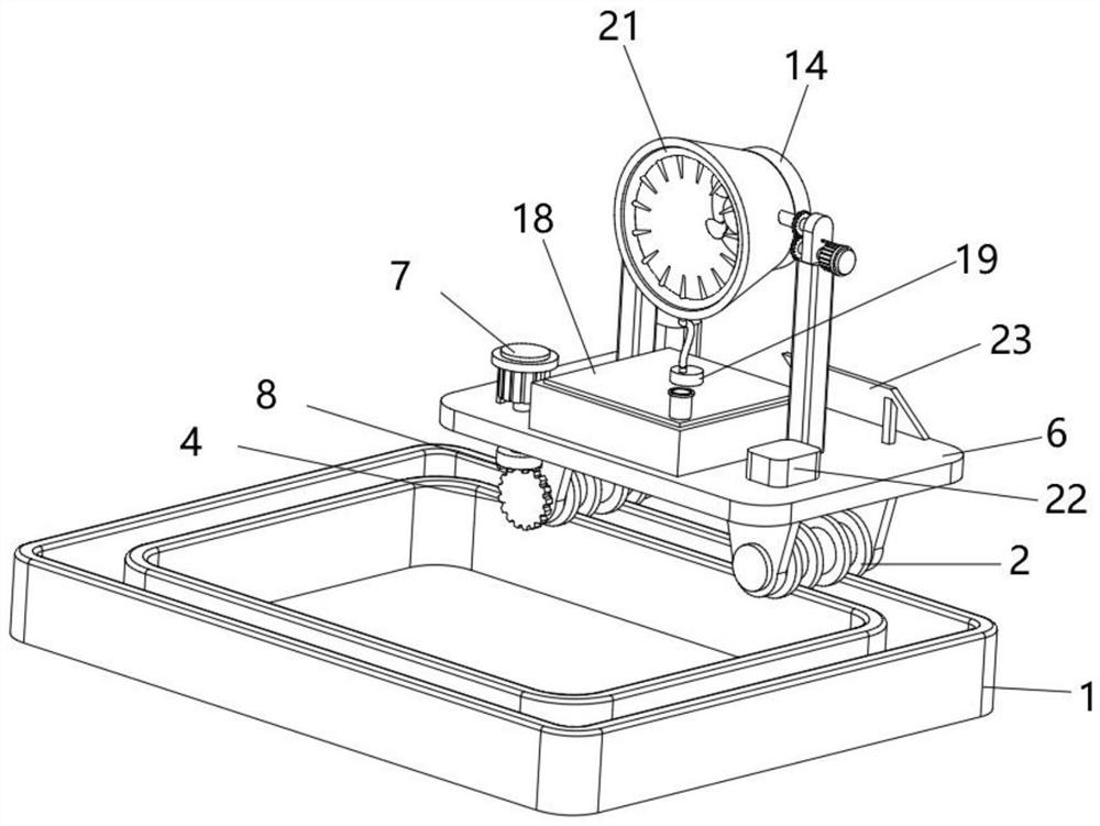
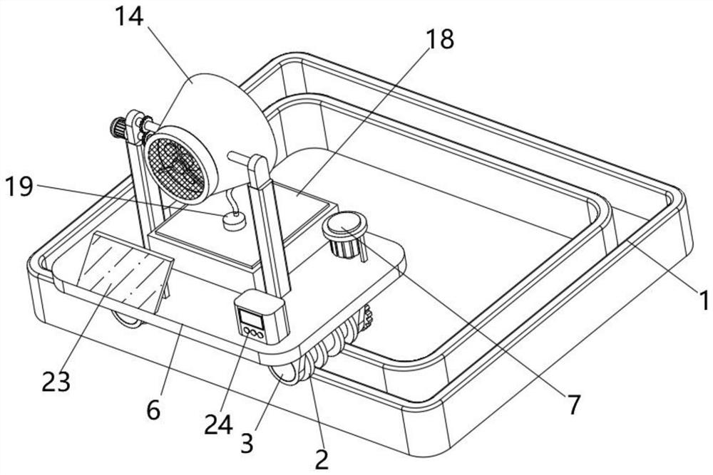
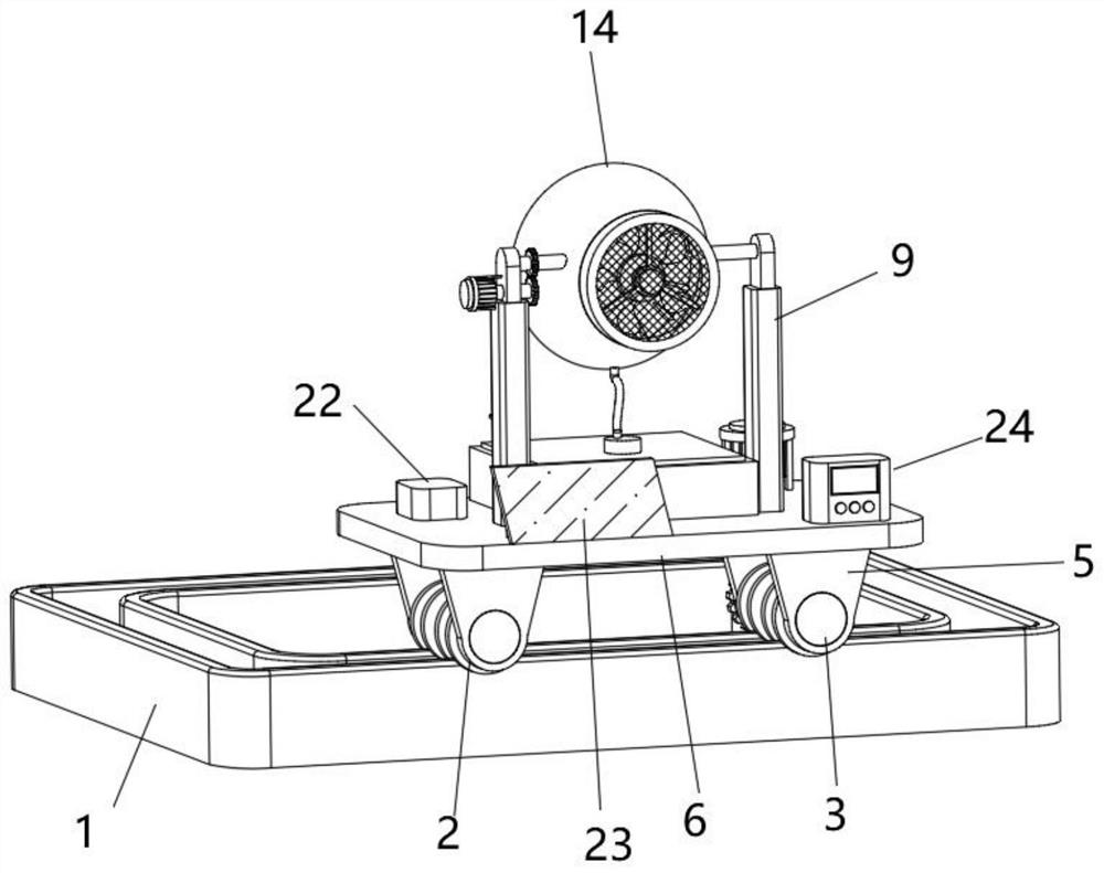
[0028] like Figure 1-5 As shown, Embodiment 1 of the present invention provides a clean energy agricultural irrigation system, including a slide rail 1, two pairs of track wheels 2 are rollingly connected on the slide rail 1, and a rotating column 3 between the two track wheels 2, one of which rotates A first driven wheel 4 is installed on one end of the column 3, a pair of support bases 5 are arranged on the rotating column 3, a support plate 6 is installed between the four support bases 5, a first drive motor 7 is installed on the support plate 6, and the first drive A bevel gear 8 is installed at the output end of the motor 7 .

[0029] The above-mentioned bevel gear 8 and the first driven wheel 4 mesh with each other, a pair of support rods 9 are installed on the support plate 6, a second drive motor 10 is installed on one of the support rods 9, and a driving wheel 11 is installed at the output end of the second drive motor 10 , the inside of the support rod 9 is connect...


PUM


Abstract

The invention belongs to the technical field of irrigation, and relates to a clean energy agricultural irrigation system which comprises a sliding rail, wherein two pairs of rail wheels are connected to the sliding rail in a rolling mode, rotating columns are arranged between the two rail wheels, a first driven wheel is installed at one end of one rotating column, a pair of supporting seats are arranged on each rotating column, a supporting plate is installed among the four supporting seats, a first driving motor is installed on the supporting plate, a bevel gear is installed at the output end of the first driving motor, connecting columns are rotationally connected to the inner side of the supporting rod, a fixing shell is installed between the two connecting columns, a third driving motor is installed in the fixing shell, a rotating head is installed at the output end of the third driving motor, a plurality of fan blades are installed on the rotating head, a water tank is installed on the supporting plate, a pump is installed on the water tank, a connecting pipe is fixedly connected to one side of the pump, and a spraying ring is installed at one end of the connecting pipe and located in the fixing shell; and a controller is installed on the supporting plate. Waste of water resources is effectively reduced, and the irrigation efficiency of the equipment is improved.

Description

technical field [0001] The invention belongs to the technical field of irrigation, in particular to a clean energy agricultural irrigation system. Background technique [0002] With the continuous progress of agricultural production, agricultural production is becoming more and more base-based. For crops, the most important thing is irrigation. [0003] The traditional irrigation methods and irrigation settings are generally flood irrigation, using electric energy sprinkler and drip irrigation, the former wastes water, the latter wastes electric energy, and the equipment cannot be moved during irrigation, only fixed irrigation can be performed, and water pipes need to be manually pulled Irrigation has virtually increased people's labor force, and the efficiency of irrigation is relatively low. Contents of the invention [0004] The present invention provides a clean energy agricultural irrigation system for solving the above problems. [0005] In order to solve the probl...

Claims


Application Information

Patent Timeline
Patent Type & Authority Applications(China)
IPC IPC(8): A01G25/09
CPCA01G25/09
Inventor 胡泽锋
Owner NEIMENGGU RUNTAI NEW ENERGY TECH CO LTD
Why Eureka
Try Eureka