Construction method of a cast-in-place prefabricated combined retaining wall structure

A construction method and retaining wall technology, which can be applied to basic structure engineering, underwater structures, artificial islands, etc., can solve the problems of earth pressure behind the wall, difficult to control deformation, large amount of earth and stone, and difficult construction, etc., to achieve The effect of reducing subgrade settlement, reducing subgrade weight and improving overall stability

Inactive Publication Date: 2015-12-30
SHENZHEN GOLDEN CENTURY ENG INDAL
View PDF7 Cites 0 Cited by
  • Summary
  • Abstract
  • Description
  • Claims
  • Application Information

AI Technical Summary

Problems solved by technology

However, due to the low rigidity of the wall, when the height of the retaining wall is too large, the construction earth and stone volume will be large, the construction will be difficult, and the soil pressure and deformation behind the wall will be difficult to control
[0005] In summary, although the existing retaining wall structure can achieve good results under suitable engineering conditions, there are still some areas to be improved.

Method used


Image

  • Construction method of a cast-in-place prefabricated combined retaining wall structure
  • Construction method of a cast-in-place prefabricated combined retaining wall structure
  • Construction method of a cast-in-place prefabricated combined retaining wall structure

Examples


Embodiment Construction

[0036] The present invention will be described in further detail below with reference to the accompanying drawings and examples. The following examples are explanations of the present invention and are not limited to the following examples.

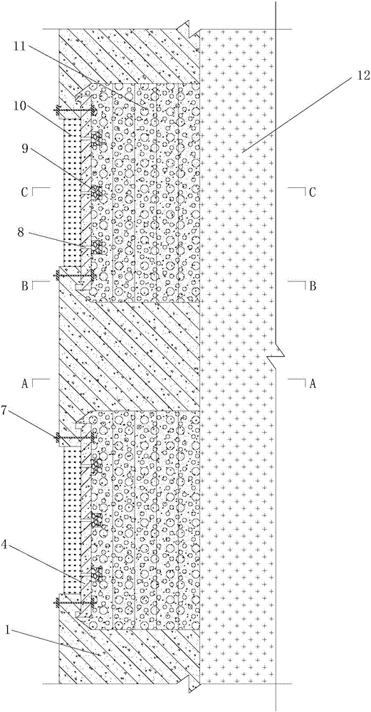
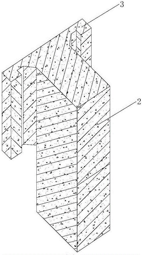
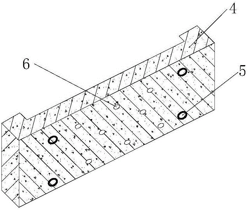
[0037] figure 1 It is a perspective view of the T-shaped column of the cast-in-place concrete short wing plate of the present invention, figure 2 It is a perspective view of the prefabricated soil retaining board of the present invention, image 3 It is a plan view of a cast-in-place prefabricated combined retaining wall structure of the present invention, Figure 4 yes image 3 Sectional view along A-A direction, Figure 5 yes image 3 Sectional view along B-B direction, Figure 6 yes image 3 Sectional view along C-C direction. refer to Figure 1~6 As shown, the cast-in-place prefabricated combined retaining wall structure is mainly composed of cast-in-place concrete short wing plate T-shaped columns 1, prefabricated earth reta...


PUM


Abstract

The invention relates to a construction method for a cast-in-place prefabricated combined type earth-retaining wall structure. The method is characterized in that the earth-retaining wall structure comprises a T-shaped column of a short cast-in-place concrete wing plate and a prefabricated retaining plate, wherein the T-shaped column of the short cast-in-place concrete wing plate consists of a short wing plate and a rib column, and concave and convex tenon-shaped grooves and screw holes are respectively formed in the short wing plate and the prefabricated retaining plate; the short wing plate and the prefabricated earth-retaining plate are fit through the concave and convex tenon-shaped grooves and are fixedly connected through a tension screw; water drain holes are formed in the prefabricated retaining plate, and vertical gravel water drain bodies are arranged at the inner side of the prefabricated retaining plate in the vertical direction of the water drain holes; a light bubble concrete soil layer is also arranged at the inner side of the prefabricated retaining plate, and the light bubble concrete soil layer is poured into a stair shape at a roadbed side; a green planting hanging basket is arranged at the outer side of the prefabricated retaining plate. The actual earth-retaining wall structure has the advantages of simple structure, good retaining effect, high construction speed, and better technical and economic benefits.

Description

technical field [0001] The invention relates to a construction method for a cast-in-place prefabricated combined retaining wall structure, which belongs to the field of highway engineering and is suitable for retaining soil when the slope cannot be normally sloped according to the design due to the influence of terrain, building red lines, adjacent buildings, etc. in highway engineering wall works. Background technique [0002] A retaining wall refers to a structure that supports fill or hillside soil and prevents the deformation and instability of the fill or soil. It is used in the retaining structure engineering of roads, railways, water conservancy, construction and other projects. There are many forms and types of retaining walls. According to their stiffness, they can be divided into two types: rigid retaining walls and flexible retaining walls. [0003] Rigid retaining wall refers to the retaining wall formed by some rigid materials such as stone masonry or concrete ...

Claims


Application Information

Patent Timeline
Patent Type & Authority Patents(China)
IPC IPC(8): E02D29/02
CPCE02D29/02
Inventor 王新泉
Owner SHENZHEN GOLDEN CENTURY ENG INDAL
Why Eureka
Try Eureka