
Bendable steel bar cutting device for house building construction

A cutting device and a steel bar technology, applied in the field of bendable steel bar cutting devices, can solve the problems of labor-intensive, steel bar springback, affecting bending effect, etc., and achieve the effect of avoiding steel bar dislocation, avoiding steel bar springback, and strong practicability.

Inactive Publication Date: 2021-09-17
郑林林
View PDF0 Cites 0 Cited by
  • Summary
  • Abstract
  • Description
  • Claims
  • Application Information

AI Technical Summary

Problems solved by technology

[0002] Steel bars are widely used in the construction field. In the process of building construction, steel bars of different sizes need to be used, which need to be cut, and sometimes bent steel bars are used. At the construction site, manual bending is generally used at present, which requires a large labor force
[0003] The existing bendable steel bar cutting device used in housing construction can bend and cut the steel bar, but the existing equipment does not perform subsequent positioning on the steel bar after bending the steel bar, which makes the steel bar rebound easily, affecting bending effect

Method used


Image

  • Bendable steel bar cutting device for house building construction
  • Bendable steel bar cutting device for house building construction
  • Bendable steel bar cutting device for house building construction

Examples


Embodiment Construction

[0034] The following embodiments will describe the present invention in detail with reference to the drawings. In the drawings or descriptions, similar or identical parts use the same symbols, and in practical applications, the shape, thickness or height of each component can be enlarged or reduced. The various embodiments listed in the present invention are only used to illustrate the present invention, and are not intended to limit the scope of the present invention. Any obvious modifications or changes made to the present invention do not depart from the spirit and scope of the present invention.

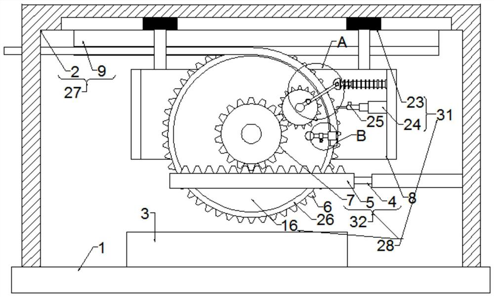
[0035] In an embodiment of the present invention, a bendable steel bar cutting device for building construction includes a bottom plate 1, and further includes:

[0036] The material guide mechanism 27 is arranged at one end of the bottom plate 1, and is used for guiding and feeding the steel bars; and

[0037] Bending mechanism 28, connected with the material guide mechanism 27...


PUM


Abstract

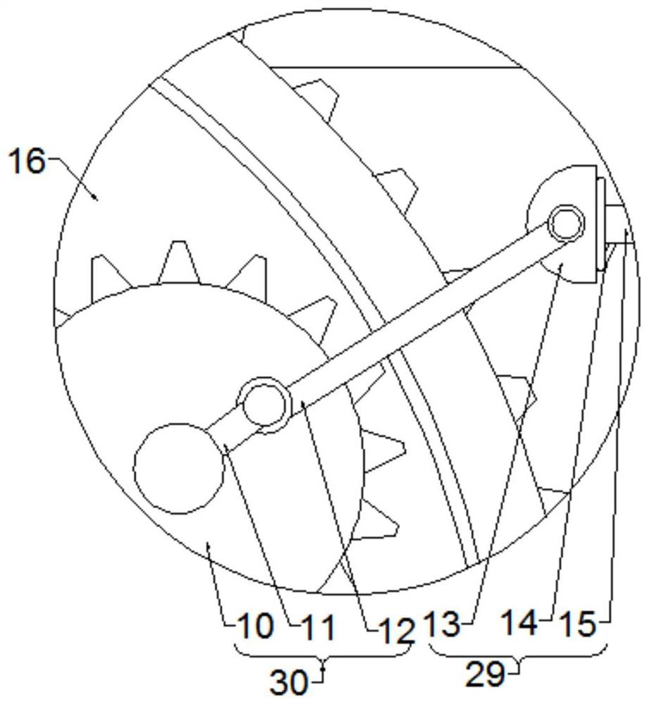
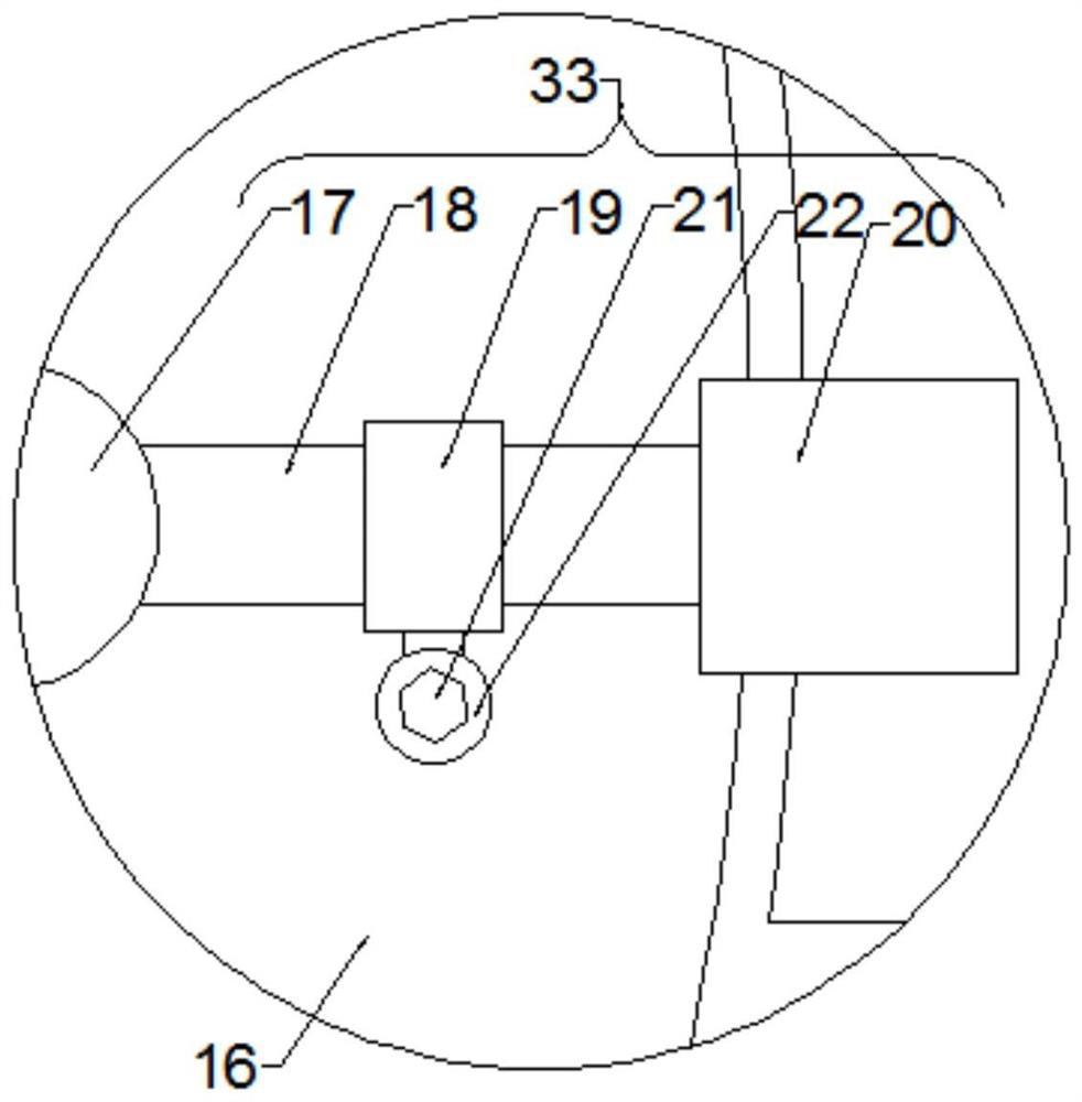
The invention discloses a bendable steel bar cutting device for house building construction, and belongs to the technical field of steel structure machining equipment. The bendable steel bar cutting device comprises a bottom plate, and further comprises a bending mechanism, a positioning mechanism and a driving mechanism; the bending mechanism is connected with a material guiding mechanism and used for bending steel bars; the positioning mechanism is connected with the bending mechanism and is used for positioning the steel bars bent by the bending mechanism, so that the rebounding of the steel bars is avoided; and one end of the driving mechanism is connected with the bending mechanism, the other end of the driving mechanism is connected with the positioning mechanism, and the driving mechanism is used for driving the positioning mechanism to continuously position the steel bars. By arranging the driving mechanism and the positioning mechanism, the bending mechanism drives the positioning mechanism to perform reciprocating hammering positioning on the steel bars in the bending process through the driving mechanism during bending; and therefore, the rebounding of the bent steel bars can be avoided, and the problem that the steel bars are prone to rebounding due to the fact that the steel bars are not subsequently positioned after being bent by some equipment is solved.

Description

technical field [0001] The invention relates to the technical field of steel structure processing equipment, in particular to a bendable steel bar cutting device used in house construction. Background technique [0002] Steel bars are widely used in the construction field. In the process of building construction, steel bars of different sizes need to be used, which need to be cut, and sometimes bent steel bars are used. At the construction site, manual bending is generally used at present, which requires a A lot of labor. [0003] The existing bendable steel bar cutting device used in housing construction can bend and cut the steel bar, but the existing equipment does not perform subsequent positioning on the steel bar after bending the steel bar, which makes the steel bar rebound easily, affecting Bend effect. Contents of the invention [0004] The object of the present invention is to provide a bendable steel bar cutting device for building construction, so as to solve...

Claims


Application Information

Patent Timeline
Patent Type & Authority Applications(China)
IPC IPC(8): B21F1/00B21F11/00
CPCB21F1/00B21F11/00
Inventor 郑林林李磊
Owner 郑林林
Learn More