A radio frequency device

A technology of radio frequency devices and lock cylinders, which is applied to waveguide devices, electrical components, circuits, etc., can solve problems such as low work efficiency, long time consumption, and easy generation of debris, so as to improve debugging efficiency, improve intermodulation and insertion loss problem effect

Active Publication Date: 2022-05-20
LUXSHARE PRECISION INDUSTRY (CHUZHOU) CO LTD
View PDF0 Cites 0 Cited by
  • Summary
  • Abstract
  • Description
  • Claims
  • Application Information

AI Technical Summary

Problems solved by technology

The existing debugging structure adopts the locking method of the screw rod and the nut, which needs to be threaded on the debugging rod, which increases the cost
At the same time, the debugging rod needs to be screwed in during debugging, and debris is likely to be generated during the screwing process
In addition, it is necessary to tighten the matching nuts to lock them, which takes a long time and reduces work efficiency

Method used


Image

  • A radio frequency device
  • A radio frequency device
  • A radio frequency device

Examples


Embodiment Construction

[0030] The present invention is described below based on examples, but the present invention is not limited to these examples. In the following detailed description of the invention, some specific details are set forth in detail. The present invention can be fully understood by those skilled in the art without the description of these detailed parts. In order not to obscure the essence of the present invention, well-known methods, procedures, procedures, components and circuits have not been described in detail.

[0031] Additionally, those of ordinary skill in the art will appreciate that the drawings provided herein are for illustrative purposes and are not necessarily drawn to scale.

[0032] Unless the context clearly requires, words like "including" and "including" throughout the application documents should be interpreted as an inclusive meaning rather than an exclusive or exhaustive meaning; that is, the meaning of "including but not limited to".

[0033] In the descr...


PUM


Abstract

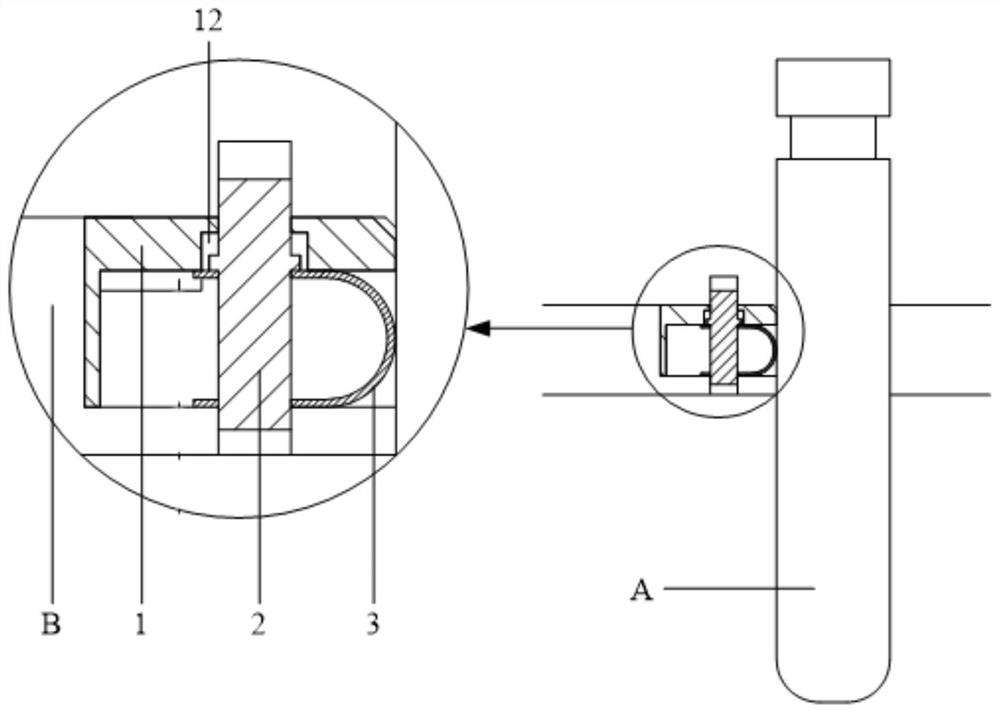
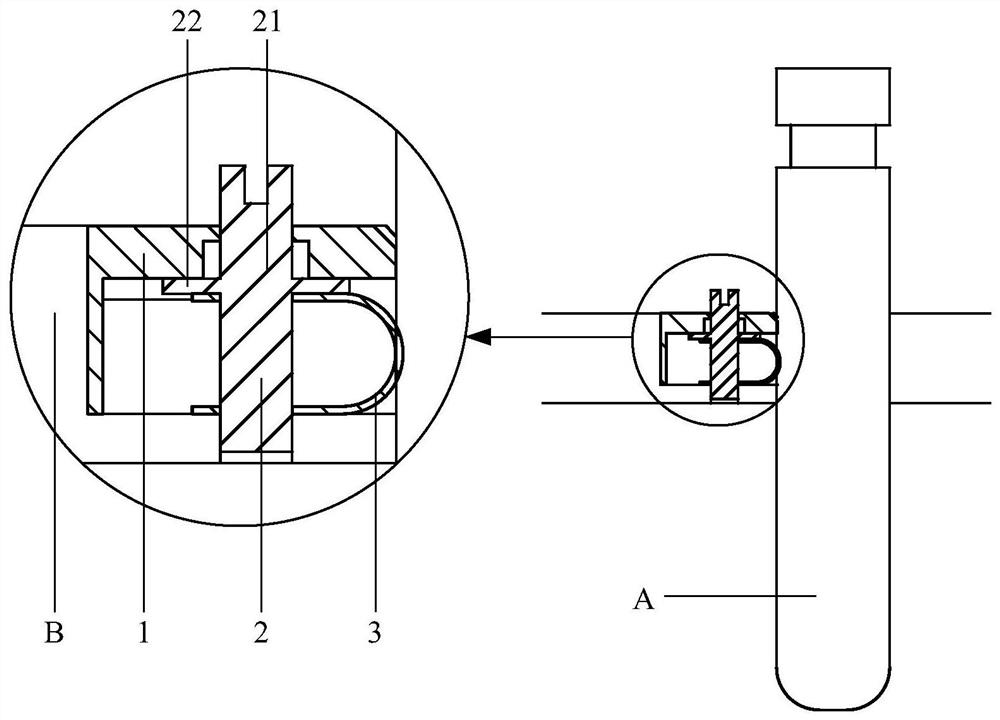
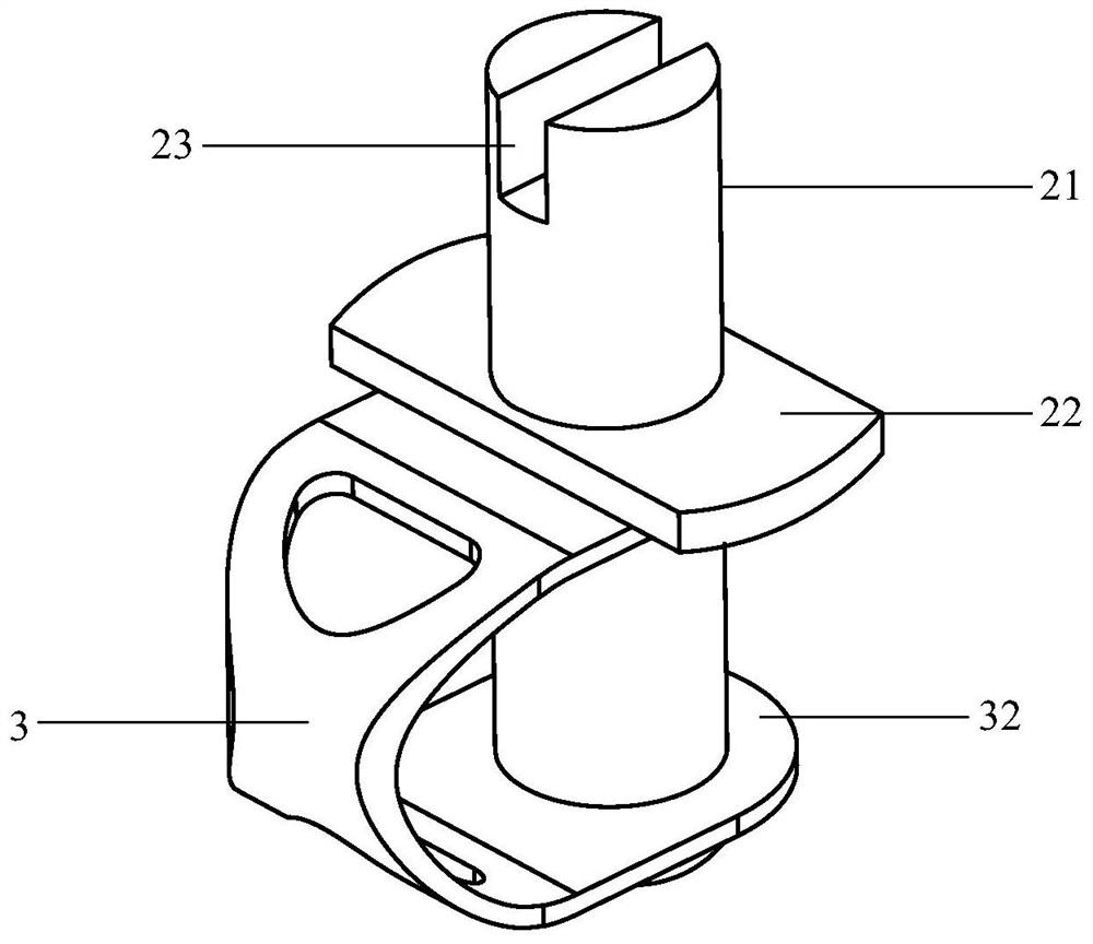
An embodiment of the present invention provides a radio frequency device, which includes a radio frequency device body, a debugging rod, a lock cylinder, and a reed. Wherein, the debugging rod is arranged in the adjustment hole of the radio frequency device body, the lock cylinder is arranged on the radio frequency device body and is located on one side of the debugging rod, and the reed includes a A curved locking part, a force receiving part connected with the lock cylinder and the curved locking part. In the radio frequency device provided by the embodiment of the present invention, force can be applied to the force receiving part through the lock cylinder, so that the bending lock part is bent and deformed under the force and abuts against the debugging rod, thereby locking the force receiving part. Debug lever. Therefore, the problems of intermodulation and insertion loss of radio frequency devices can be improved, and the debugging efficiency is greatly improved.

Description

technical field [0001] The invention relates to the field of locking structures of communication equipment, in particular to a radio frequency device. Background technique [0002] For RF products, including but not limited to filters, duplexers, combiners and tower mount amplifiers, etc., a debugging rod is usually used for debugging. The existing debugging structure adopts a locking method in which the screw rod and the nut cooperate, and threads need to be provided on the debugging rod, which increases the cost. At the same time, the debugging rod needs to be screwed in during debugging, and debris is likely to be generated during the screwing process. In addition, it is necessary to tighten the matching nuts to lock them, which takes a long time and has low work efficiency. Contents of the invention [0003] In view of this, the present invention provides a radio frequency device, which locks the debugging rod through the bending deformation of the reed, thereby impr...

Claims


Application Information

Patent Timeline
Patent Type & Authority Patents(China)
IPC IPC(8): H01P1/00
CPCH01P1/00
Inventor 宋振国高贵平孙兴华
Owner LUXSHARE PRECISION INDUSTRY (CHUZHOU) CO LTD
Why Eureka
Try Eureka