A broadband line combiner

A combiner and broadband technology, applied in the field of communication, can solve the problems of poor consistency, high production cost, difficult installation, etc., and achieve the effect of reducing production cost, good return loss, and wide-band bandwidth

Active Publication Date: 2019-11-12
PROSE TECH CO LTD
View PDF5 Cites 0 Cited by
  • Summary
  • Abstract
  • Description
  • Claims
  • Application Information

AI Technical Summary

Problems solved by technology

[0002] At present, most of the commonly used radio frequency signal combiners adopt the air cavity structure, and are combined or divided for several single frequency bands, such as a high-power broadband combiner disclosed in the Chinese utility model patent with the announcement number CN201656922U. The power capacity and reliability of the combiner are improved, but due to the structure of microstrip line plus inductive welding, the production cost is high, the consistency is poor, and the installation is difficult. complicated process

Method used


Image

  • A broadband line combiner
  • A broadband line combiner
  • A broadband line combiner

Examples


Embodiment Construction

[0014] The technical solution of the present invention will be described in further detail below in conjunction with the accompanying drawings.

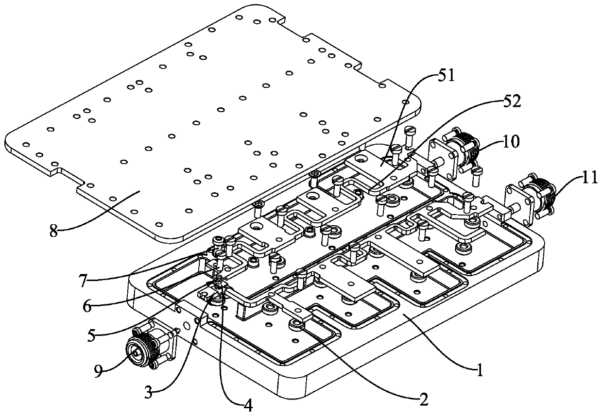
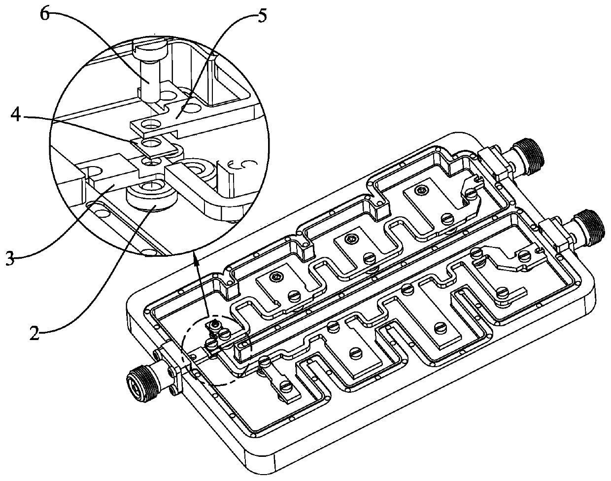
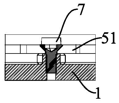
[0015] Such as figure 1 As shown, a broadband line combiner provided by the present invention includes a cavity 1 and a cover plate 8 fixed on the cavity, and one side of the cavity 1 is provided with a The input connector is provided with two-way input in this embodiment, which corresponds to the input connector 10 and the input connector 11 respectively; while the other side is provided with an output connector 9 for outputting the combined signal, the cavity 1, the cover The board 8 and the output connector 9 form a shielding space. Wherein the cavity 1 is at least provided with a first filter and a second filter. In this embodiment, the first filter is a band-stop bandline filter, and the second filter is a band-line high-pass filter; further, the band-stop bandline filter includes a The first stripline 3 on 1, the stripline h...


PUM


Abstract

The invention discloses a wideband line combiner. The wideband line combiner comprises a cavity and a cover plate fixed on the cavity, wherein input connectors as input ends of different frequency band signals are arranged on one side of the cavity; an output connector for outputting a combined signal is arranged on the other side of the cavity; at least a first filter and a second filter are arranged inside the cavity; the first filter comprises a first band line fixed on the cavity; the second filter comprises a second band line fixed on the cavity; one end of the first band line and one end of the second band line are coupled, while the other ends of the first band line and the second band line are connected with the corresponding input connectors. The wideband line combiner has a relatively wide frequency band, can achieve good return loss, insertion loss, isolation, intermodulation and power capacity within the frequency band.

Description

technical field [0001] The solution relates to a combiner, which belongs to the technical field of communication, and in particular to a broadband line combiner. Background technique [0002] At present, most of the commonly used radio frequency signal combiners adopt the air cavity structure, and are combined or divided for several single frequency bands, such as a high-power broadband combiner disclosed in the Chinese utility model patent with the announcement number CN201656922U. The power capacity and reliability of the combiner are improved, but due to the structure of microstrip line plus inductive welding, the production cost is high, the consistency is poor, and the installation is difficult. The process is complicated. Contents of the invention [0003] In view of the above-mentioned problems in the prior art, the object of the present invention is to provide a broadband line combiner. The combiner realized by the broadband road combiner has a relatively wide fr...

Claims


Application Information

Patent Timeline
Patent Type & Authority Patents(China)
IPC IPC(8): H01P1/213
Inventor 曹旭飞程晓辉尹泽霍永兴
Owner PROSE TECH CO LTD
Why Eureka
Try Eureka