Circuit and method for interference reduction

A circuit and interference signal technology, applied in the direction of improving amplifiers to reduce nonlinear distortion, electrical components, components of amplifiers, etc., to achieve the effects of reducing susceptibility, reducing intermodulation, and reducing requirements

Active Publication Date: 2014-09-17
TELEFON AB LM ERICSSON (PUBL)
View PDF5 Cites 0 Cited by
  • Summary
  • Abstract
  • Description
  • Claims
  • Application Information

AI Technical Summary

Problems solved by technology

Thus, intermodulation distortion is a serious problem for such transmitters and needs to be dealt with if performance requirements should be met

Method used


Image

  • Circuit and method for interference reduction
  • Circuit and method for interference reduction
  • Circuit and method for interference reduction

Examples


Embodiment Construction

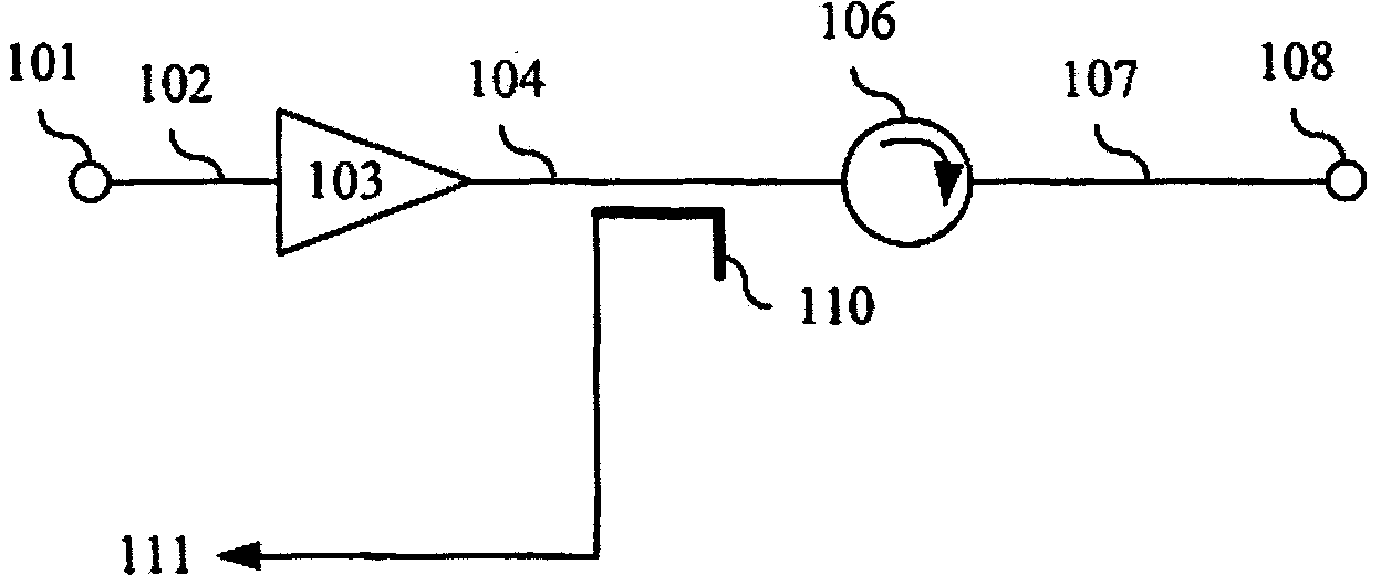
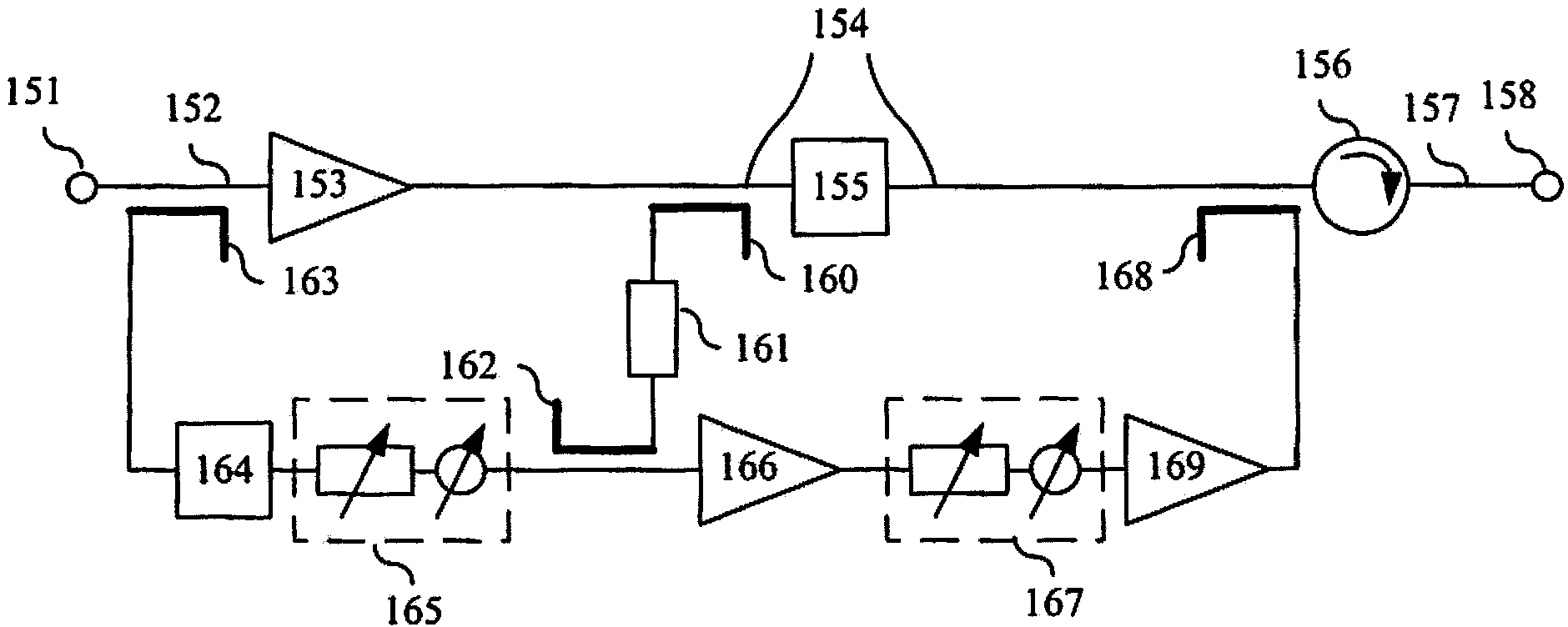
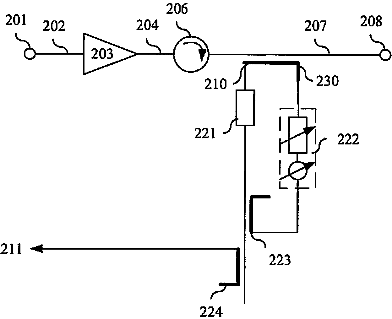
[0044] In the following, an embodiment of the present invention using a linearization loop will be described, wherein the linearization loop includes not only the power amplifier (PA) of the radio frequency (RF) circuit, but also includes the application between the PA of the RF circuit and the antenna port. isolators (for example, circulators). Thus, according to some embodiments, the PA is isolated from the antenna port, and the linearization loop feedback coupling point is located after (outside) the isolator. This linearization may be performed using any suitable known or future linearization method.

[0045] It should be understood that other elements may also be present between the PA and the antenna port according to some embodiments. For example, a filter can be located between the isolator and the antenna port.

[0046] In order to isolate such a linearization loop arrangement from (or at least minimize the impact of) interfering signals associated with the antenna ...


PUM


Abstract

A radio frequency transmitter comprising: an amplifier; an antenna port; an isolator adapted to isolate the output of said amplifier from interfering signals at said antenna port; a linearization loop; and a transmission line comprising a first portion (coupling a signal source to input of the amplifier), a second section (coupling the output of the amplifier to the input of the isolator) and a third section (coupling the output of the isolator to the antenna port). The linearization loop is adapted to reduce non-linearity of the isolator. The radio frequency transmitter also includes an interference reduction circuit adapted to reduce the influence of the interference signal on the linearization loop.

Description

technical field [0001] The present invention relates generally to the field of interference reduction in radio frequency transmitter circuits. Background technique [0002] In general, the performance requirements of radio frequency (RF) transmitter circuits can be high and can relate to, for example, noise generation, susceptibility to external interference, linearity in the operating range, and the like. The RF performance requirements of multicarrier transmitters are typically extremely high. To meet this requirement, various solutions (individually or in combination) can be employed. [0003] For example, the output power amplifier (PA) may need to be linearized (eg by means of a linearization loop) in order to possibly meet requirements related to linearity. [0004] Furthermore, to possibly meet requirements related to susceptibility to interference, it may be necessary to couple the PA and linearization loop with interfering signals at the antenna port (e.g. signals...

Claims


Application Information

Patent Timeline
Patent Type & Authority Patents(China)
IPC IPC(8): H04B1/04H03F1/32
CPCH03F1/3229H03F3/24H04B2001/045H04B1/0475Y10T29/49117H03F1/02
Inventor 斯彭迪姆·达利皮
Owner TELEFON AB LM ERICSSON (PUBL)
Why Eureka
Try Eureka