A cavity type phase shifter

A phase shifter and cavity technology, applied in waveguide-type devices, antennas, circuits, etc., can solve the problems affecting the performance and deformation of the phase shifter, and avoid blackening of solder joints, low intermodulation, and good welding effect. Effect

Active Publication Date: 2019-05-10
WUHAN HONGXIN TELECOMM TECH CO LTD
View PDF8 Cites 0 Cited by
  • Summary
  • Abstract
  • Description
  • Claims
  • Application Information

AI Technical Summary

Problems solved by technology

This method is easy to cause the dielectric board to be supported by the connecting pins during series connection and cause deformation, which affects the performance of the phase shifter

Method used


Image

  • A cavity type phase shifter
  • A cavity type phase shifter
  • A cavity type phase shifter

Examples


Embodiment Construction

[0050] In order to explain the technical solutions of the embodiments of the present invention more clearly, the technical solutions of the present invention will be described in detail below in conjunction with the accompanying drawings and embodiments. Obviously, the embodiments and drawings described below are only a part of the embodiments of the present invention. For those of ordinary skill in the art, without any creative work, everything made based on the technical solutions of the present invention Modifications, improvements, etc. are all included in the protection scope of the present invention.

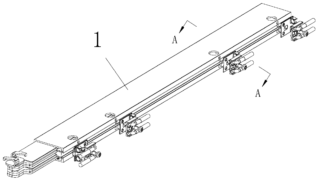
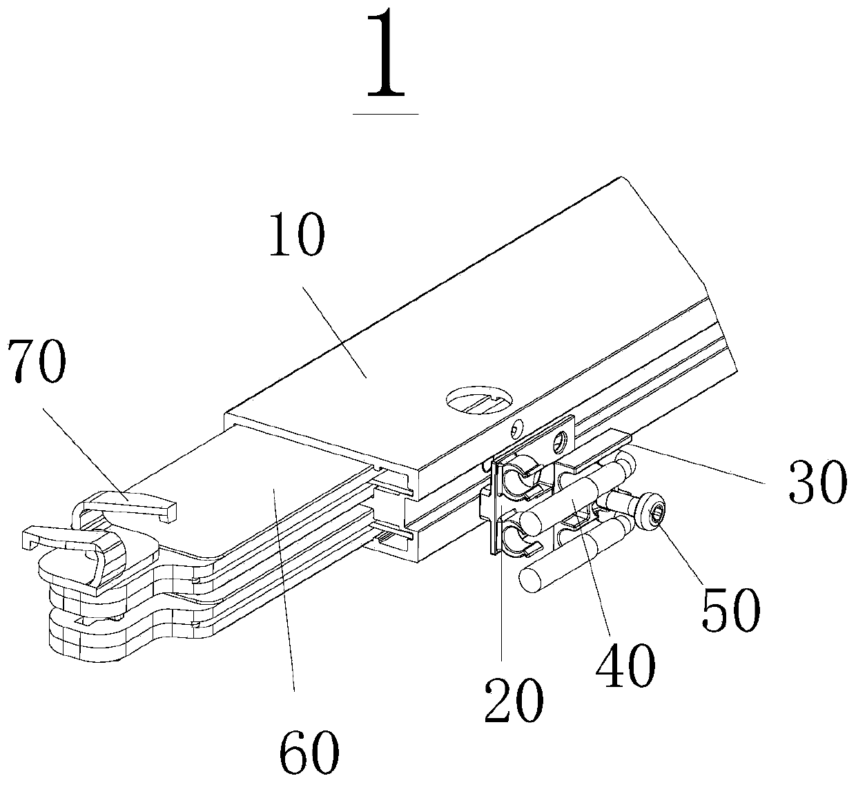
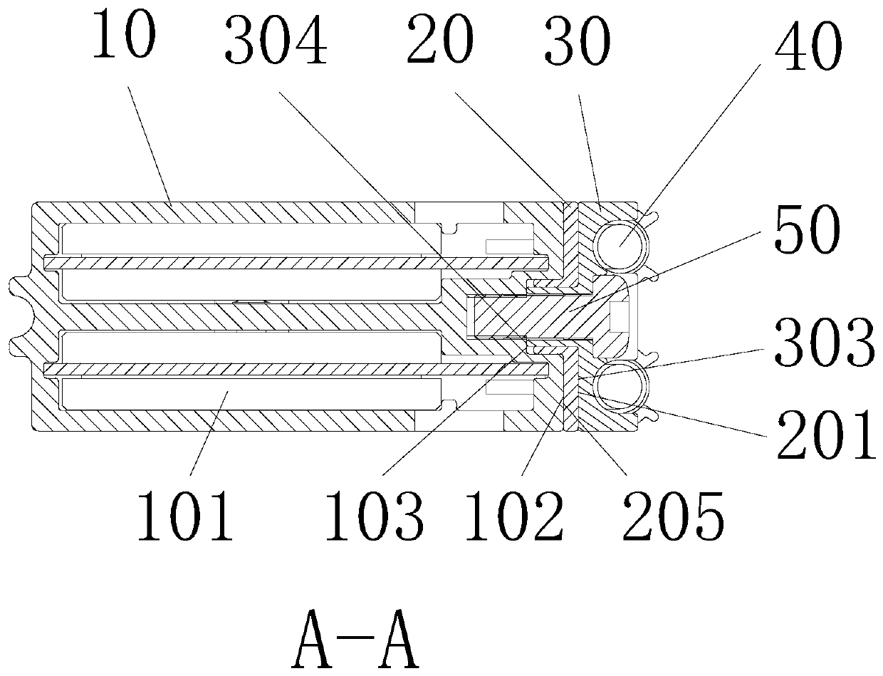
[0051] Such as Figure 1 to Figure 8 As shown, a phase shifter 1 includes a cavity 10, an insulating card 20, a feeder seat 30, a dielectric plate 60, a drive pin 70, and a coaxial cable 40. The corresponding microwave network is set up in specific implementation, and is used where necessary Screw 50 connection.

[0052] The side wall outside the cavity is a concave groove. O...


PUM


Abstract

The invention provides a cavity phase shifter which comprises a cavity, edge insulators, feeder bases, dielectric plates, a microwave network, a drive pin, and coaxial cables. The drive pin connects the multiple dielectric plates in series. The cavity contains two sub-cavities, and the two inner sidewalls of each sub-cavity are provided with guide slots for fixing the microwave network. One side of the outer sidewall of the cavity is provided with a groove, and the groove is provided with a screw hole and outer sidewall wire holes at positions corresponding to the ports of the microwave network. The middle of the front of each feeder base is provided with a screw fixing hole, and two welding slots are arranged above and below each screw fixing hole respectively. The end of each welding slot is provided with a welding slot wire hole corresponding to the groove of the cavity. The backs of the feeder based are provided with bosses. The fronts of the edge insulators are provided with through holes corresponding to the bosses. The upper and lower sides of each through hole are provided with edge insulator wire holes corresponding to the feeder bases. Through innovative design of the cavity component and the drive pin of the phase shifter, the cavity phase shifter has the characteristics of low cost, low inter-modulation and small size, and is simple in structure, easy to assemble and suitable for mass production.

Description

Technical field [0001] The invention relates to the field of mobile communication base station antennas, and in particular to a cavity type phase shifter. Background technique [0002] The phase shifter is the core component of the electronically adjustable antenna. The electronically adjustable antenna is mechanically linked by the phase shifter to change the relative phase change between the antenna radiating elements, thereby realizing the adjustment of the beam tilt angle and achieving the goal of adjusting and optimizing network coverage. [0003] In the antenna structure, the phase shifter is generally placed on the back of the antenna, and the microwave network inevitably produces backward radiation, which has a bad influence on the front-to-back ratio of the antenna. Therefore, generally, shielding measures are adopted for the microwave network of the phase shifter to reduce the influence of the deterioration of the front-to-back ratio of the antenna caused by the backward ...

Claims


Application Information

Patent Timeline
Patent Type & Authority Patents(China)
IPC IPC(8): H01P1/18H01Q3/32
CPCH01P1/18H01Q3/32
Inventor 江峰骆胜军吴卫华熊锡刚张维国
Owner WUHAN HONGXIN TELECOMM TECH CO LTD
Why Eureka
Try Eureka