A device for constructing myopia animal model
An animal model and myopia technology, applied in the field of medical devices, can solve problems such as the inability to effectively study the correlation between light perception and myopia, and the myopia model without photosensitive abnormalities, so as to increase the scope of use, save storage space, and use flexibly Effect
- Summary
- Abstract
- Description
- Claims
- Application Information
AI Technical Summary
Problems solved by technology
Method used
Image

Examples
Embodiment 1
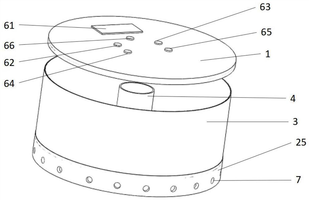
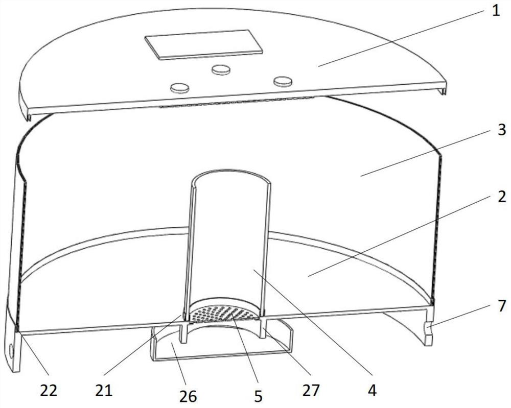
[0056] A myopia animal model constructs instruments, such as Figure 1-8 It includes a light board 11 with different color lamps, controlling the control structure of different color lamps on the lampboard 11; accommodating the accommodating groove 4 of the experimental animal, disposed on the periphery of the accommodating groove 4; wherein the lampboard 11 The top end of the accommodating groove 4 is provided to accommodate the groove 4 as the center of the accommodating groove 4 is disposed around the outer edge distance of the housing groove 4; the screen 5 is provided at the bottom of the accommodating groove 4; at the top of the housing groove 4 The vent hole 7 is provided in the structure; the tank 4 is provided as a transparent sidewall. By controlling the different lamps 11 on the lamp plate 11, the intensity and time of the light emission is controlled, and the effect of forming myopia model animal model by controlling the sensation. By setting the screen 5, there is a gu...
Embodiment 2
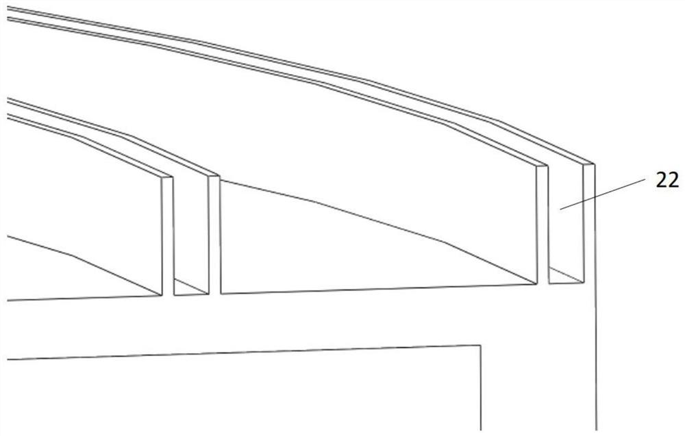
[0068] Such as Figure 9-12 On the basis of the implementation 1, the cylindrical ring 3 or the housing groove 4 is disposed onto a chassis 2, and is set to: a small groove 21 and a plurality of short grooves 22 on a chassis 2; or setting A plurality of short grooves one 21 is set to a plurality of small grooves 2 22, and corresponding to the accommodating grooves 4 and cylindrical ring 3 of different diameters.
Embodiment 3
[0070] Such as Figure 15 On the basis of Example 1-2, the change of the housing groove 4 and the cylindrical ring 3 and the chassis 2 and the lamp plate accommodating the top 1 are each combined, specifically: the magnetic loop one 23 of the suction accommodating groove 4 on the chassis 2 and The magnetic ring 2 24 of the adsorption placed column ring 3, the magnetic loop and the chassis are arranged horizontally, and the magnetic suction protruding ring 41 corresponding to the magnetic cycle is disposed at the bottom of the receiving groove 4 and the cylindrical ring 3.
[0071] Set different models of chassis 2, and corresponding to the visual reference target 31 and the cylindrical ring 3, the distance between the visual 31 and the accommodating groove 4, each chassis 2 sets a suction housing groove 4. The magnetic ring 1 23 and a magnetic suction ring 2 24 of the adsorption placed column ring 3.
PUM
 Abstract
Description
Claims
Application Information
 - R&D
- Intellectual Property
- Life Sciences
- Materials
- Tech Scout
- Unparalleled Data Quality
- Higher Quality Content
- 60% Fewer Hallucinations
Browse by: Latest US Patents, China's latest patents, Technical Efficacy Thesaurus, Application Domain, Technology Topic, Popular Technical Reports.
© 2025 PatSnap. All rights reserved.Legal|Privacy policy|Modern Slavery Act Transparency Statement|Sitemap|About US| Contact US: help@patsnap.com