Electronic product display device
A technology for display devices and electronic products, applied in display stands, display hangers, display shelves, etc., can solve the problems of not supporting human observation and product display, and achieve the effect of enhancing the display effect
- Summary
- Abstract
- Description
- Claims
- Application Information
AI Technical Summary
Problems solved by technology
Method used
Image
Examples
Embodiment 1
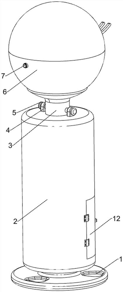
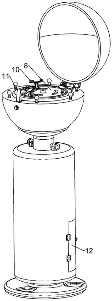
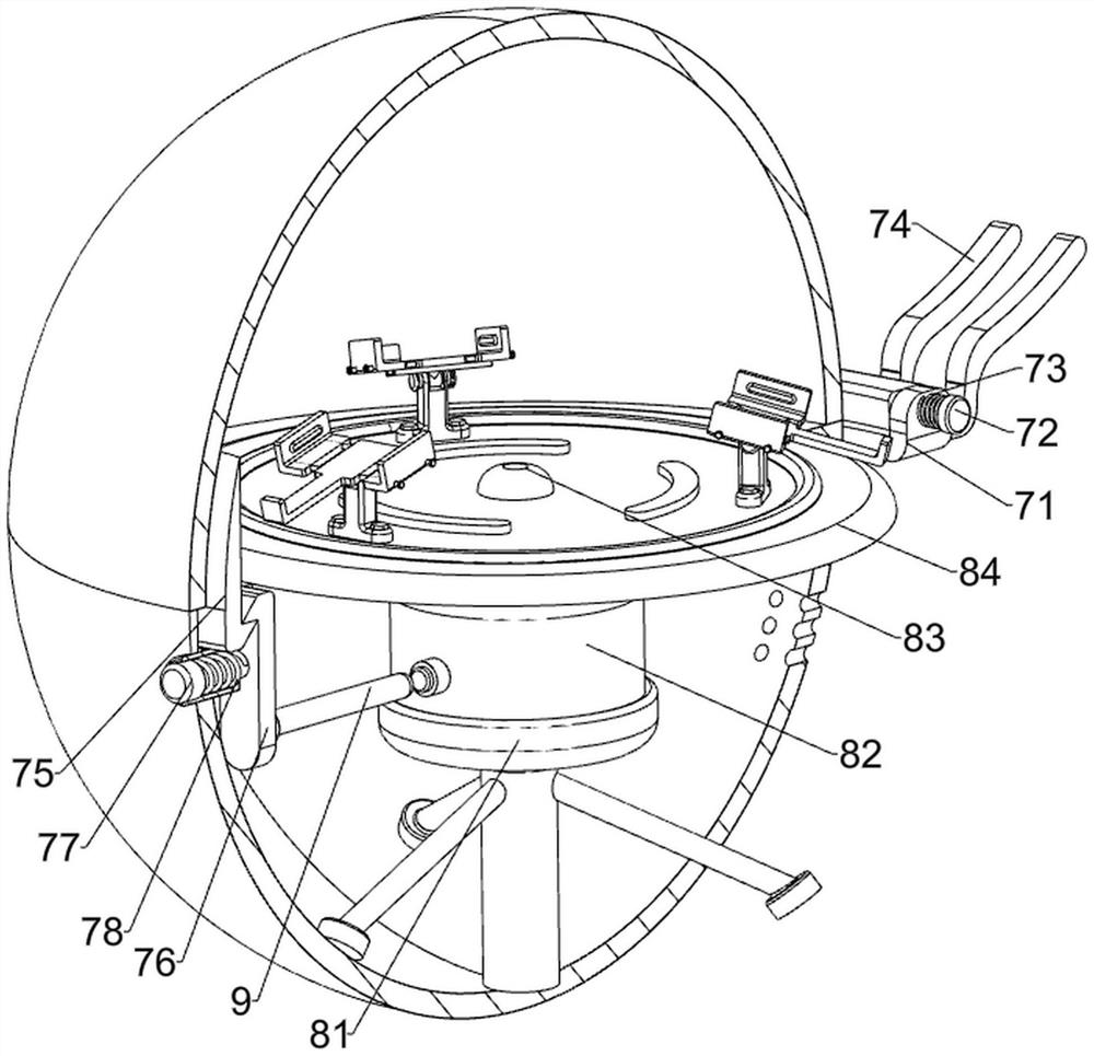
[0025] An electronic product display device, such as Figure 1 to Figure 3 As shown, it includes a base 1, a mounting column 2, a bracket 3, a guide block 4, a positioning pin 5, a display stand 6, a locking mechanism 7, and a rotating display mechanism 8. The top of the base 1 is provided with a mounting column 2, and the top of the mounting column 2 The bracket 3 is placed slidingly, the top of the mounting column 2 is symmetrically provided with a guide block 4, and the guide block 4 is slidingly provided with a positioning pin 5, and the positioning pin 5 is slidably matched with the bracket 3, and the top of the bracket 3 is provided with a display stand 6 , The display stand 6 is provided with a locking mechanism 7, and the bottom of the inner wall of the display stand 6 is provided with a rotating display mechanism 8.
[0026] The locking mechanism 7 includes a support frame 71, a steering shaft 72, a torsion spring 73, a limit block 74, a first wedge block 75, a second...
Embodiment 2
[0030] On the basis of Example 1, such as Figure 4 , Figure 7 with Figure 8 As shown, a rotation control mechanism 9 is also included. The rotation control mechanism 9 includes a motor control switch 91, a mounting block 92 and a trigger lever 93. The front side of the servo motor 82 is provided with a motor control switch 91, and the rear side of the second wedge block 76 is lower. A mounting block 92 is provided, and a trigger lever 93 is provided on the rear side of the mounting block 92, and the trigger lever 93 cooperates with the motor control switch 91.
[0031] Also include display product placement adjustment mechanism 10, display product placement adjustment mechanism 10 includes installation frame 101, adjustment shaft 102, placement bracket 103, anti-skid pad 104, installation groove plate 105, gear 106, first rack 107 and second Rack 108, three installation frames 101 are arranged on the outer side of the top of the placement plate 84, and the top of the inst...
Embodiment 3
[0034] On the basis of Example 2, such as Figure 5 with Image 6 As shown, it also includes a display effect strengthening mechanism 11. The display effect strengthening mechanism 11 includes an ambient light 111, an installation base 112, a wire 113, a wire slot 114, a light control switch 115 and a toggle lever 116. There is a wire trough 114 connected between them, and a light control switch 115 is provided on the front side of the top of the wire trough 114, and 6 wires 113 are connected to the wire trough 114, and the other end of the wire 113 is connected to the installation base 112, and the top of the installation base 112 is provided with an atmosphere The lamp 111 is provided with a toggle lever 116 at the bottom of the placement tray 84, and the toggle lever 116 cooperates with the light control switch 115.
[0035] Also includes exhibit storage mechanism 12, exhibit storage mechanism 12 includes hinge 121, cabinet door 122 and handle 123, mounting column 2 bottom...
PUM
 Abstract
Description
Claims
Application Information
 - R&D
- Intellectual Property
- Life Sciences
- Materials
- Tech Scout
- Unparalleled Data Quality
- Higher Quality Content
- 60% Fewer Hallucinations
Browse by: Latest US Patents, China's latest patents, Technical Efficacy Thesaurus, Application Domain, Technology Topic, Popular Technical Reports.
© 2025 PatSnap. All rights reserved.Legal|Privacy policy|Modern Slavery Act Transparency Statement|Sitemap|About US| Contact US: help@patsnap.com


