
Unit type stone curtain wall fine adjustment system and installation method

A stone curtain wall and unitized technology, which is applied in the processing of walls, building materials, building components, etc., can solve problems such as hole position deviation, and achieve the effects of eliminating hole position deviation, ensuring reliability, and convenient installation

Active Publication Date: 2021-10-01
苏州苏明装饰股份有限公司
View PDF6 Cites 0 Cited by
  • Summary
  • Abstract
  • Description
  • Claims
  • Application Information

AI Technical Summary

Problems solved by technology

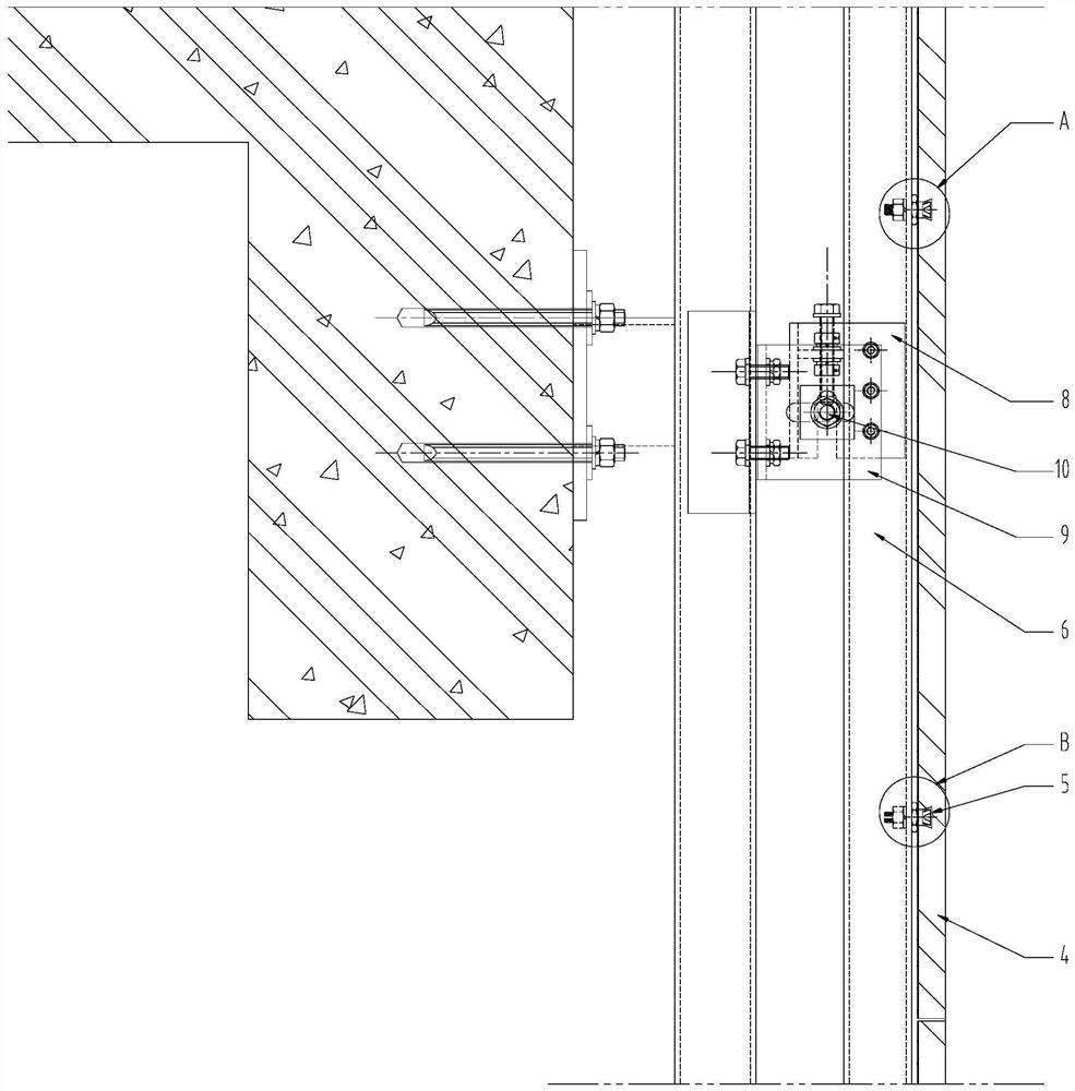
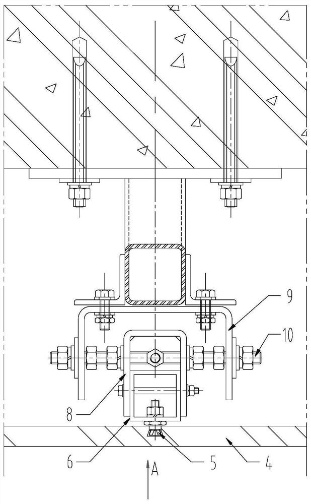
[0004] The purpose of the present invention is to solve the problem of hole location deviation in the current unitized stone curtain wall, and provide a fine-tuning system for the unitized stone curtain wall and its installation method, which can effectively eliminate the installation deviation of hole parts and improve construction efficiency

Method used


Image

  • Unit type stone curtain wall fine adjustment system and installation method
  • Unit type stone curtain wall fine adjustment system and installation method
  • Unit type stone curtain wall fine adjustment system and installation method

Examples


Embodiment 1

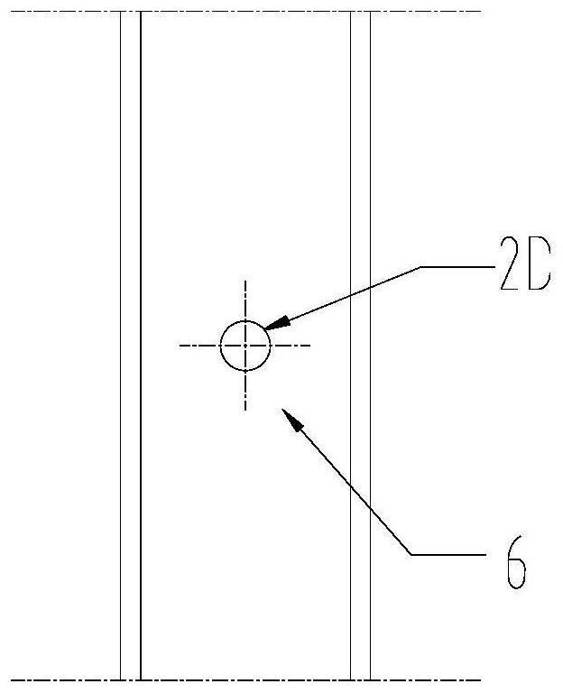
[0044] Embodiment one: if figure 1 and Figure 8 As shown, the hole position deviation adjustment structure includes a column 6, and the column 6 is as Figure 5 As shown, it includes a front side wall 6A, a rear side wall 6B, a left side wall 6C and a right side wall 6D; it is surrounded by the front side wall 6A, the rear side wall 6B, the left side wall 6C and the right side wall 6D to form two ends through In the hollow area, a notch 1A is provided on the front side wall 6A of the column 6 . The notch 1A passes through the bottom end of the column 6 from the top end of the column 6 . The setting of the notch 1A will reduce the strength of the column 6. In order to avoid this problem, a partition 6E is also provided in the hollow area. One end of the partition 6E extends to the left side wall 6C, and the other end extends to the right side wall 6D. Surrounded by the partition 6E, the left side wall 6C and the right side wall 6D, a cavity with both ends penetrating and ci...

Embodiment 2

[0055] Embodiment two, see attached Figure 15 and Figure 16 As shown, this embodiment is basically the same as Embodiment 1, except that the aluminum alloy column 6 is the same as the traditional aluminum alloy column, and consists of a front side wall 6A, a rear side wall 6B, a left side wall 6C and a right side wall 6D Surrounding and forming a hollow cavity with both ends penetrating and closed in the circumferential direction, vertical oblong holes 12 are provided at the positions corresponding to the upper fulcrum A and the lower fulcrum B of the front side wall 6A.

[0056] The eccentric washer 2 only has an inner limiting portion 2B and an inserting portion 2A. At the upper fulcrum A, an outer gasket 11 independent of the eccentric gasket 2 is provided on the outer surface of the front side wall 6A, and the eccentric gasket 2, the front side wall 6A of the column 6 and the outer gasket 11 are simultaneously connected by a set screw 7, The limit between the eccentric...


PUM


Abstract

The invention discloses a unit type stone curtain wall fine adjustment system and an installation method, and belongs to the field of building curtain walls. The system aims to quickly and effectively eliminate the installation deviation of hole position parts. The system comprises a stand column, and a long-strip-shaped notch is formed in the supporting wall of the stand column; an upper fulcrum and a lower fulcrum of the stand column comprise eccentric gaskets, the cross section of an insertion part of each eccentric gasket is circular, an installation hole penetrating in the axial direction is formed in each insertion part, and the center of each installation hole deviates from the center of the corresponding insertion part; the insertion part is inserted into the notch; in the annular direction of the insertion part, the insertion part is movably matched with the notch; and in the extending direction of the notch, the insertion part is movably matched with the notch, and the eccentric gasket of the upper fulcrum is fixed to the stand column through a connecting piece. According to the method, the hole position deviation between the stone back bolt hole position and the aluminum alloy profile hole position is automatically eliminated in the installation process, it is guaranteed that the stone back bolt hole can be smoothly aligned, and the installation efficiency is improved.

Description

technical field [0001] The invention belongs to the field of building curtain walls, in particular to a fine-tuning system and an installation method for a unitized stone curtain wall. Background technique [0002] The unitized stone curtain wall is to fix multiple stone panels on the profile skeleton through back bolts to form a complete curtain wall unit, and then hoist the curtain wall unit as a whole and connect it with the main structure. The unitized stone curtain wall can effectively improve the efficiency of site installation and the assembly accuracy of stone panels, so it is widely used. [0003] In the current unitized stone curtain wall, the connection method between the stone panel and the profile skeleton is as follows: figure 1 , figure 2 and image 3 As shown, the back bolt hole is processed on the back of the stone panel, and the suitable back bolt through hole is drilled at the corresponding position of the profile skeleton. The head of the back bolt is...

Claims


Application Information

Patent Timeline
Patent Type & Authority Applications(China)
IPC IPC(8): E04B2/96E04G21/18
CPCE04B2/96E04G21/18E04G21/1841
Inventor 计苓
Owner 苏州苏明装饰股份有限公司
Learn More