
Image fusion method based on linearity comparison, storage medium and terminal equipment

An image fusion and linearity technology, applied in the field of image fusion, can solve the problems of heavy workload, poor fusion effect, and easy ripples in the transition zone, etc., and achieve the effect of flexible and convenient application, reduced calibration workload, and high calculation efficiency

Active Publication Date: 2021-10-01
NORTHWEST INST OF NUCLEAR TECH
View PDF3 Cites 0 Cited by
  • Summary
  • Abstract
  • Description
  • Claims
  • Application Information

AI Technical Summary

Problems solved by technology

[0005] The present invention solves the threshold comparison method commonly used in the fusion of two images with high and low gain. The workload before use is large. If the threshold drifts due to changes in the external environment during use, it must be re-calibrated, and during normal fusion, the saturation area Ripples are prone to appear in the transition zone of the unsaturated region and the unsaturated region, resulting in a technical problem of poor fusion effect. An image fusion method based on linearity comparison, a computer-readable storage medium, and a terminal device are provided.

Method used


Image

  • Image fusion method based on linearity comparison, storage medium and terminal equipment
  • Image fusion method based on linearity comparison, storage medium and terminal equipment
  • Image fusion method based on linearity comparison, storage medium and terminal equipment

Examples


Embodiment Construction

[0031] The technical solutions of the present invention will be clearly and completely described below in conjunction with the embodiments of the present invention and the accompanying drawings. Apparently, the described embodiments do not limit the present invention.

[0032] The invention proposes a large dynamic range image fusion method based on linearity comparison. When the method is used for large dynamic range image fusion, threshold calibration is not required, and the fusion process is not easily affected by the external environment, and the fusion calculation efficiency is high.

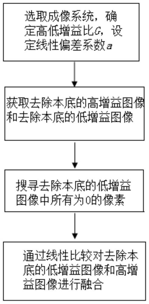
[0033] see figure 1 , the following is the specific execution process of the fusion method of the present invention:

[0034] Step 1: Select an imaging system that can generate two images, a high-gain image and a low-gain image, determine the high-to-low gain ratio G, and set the linear deviation coefficient a;

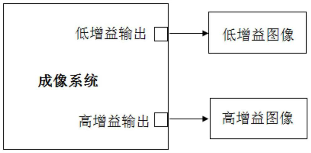
[0035] Among them, such as figure 2 As shown, the imaging system is equipp...


PUM


Abstract

The invention belongs to an image fusion method. In order to solve the technical problems that a threshold comparison method commonly adopted for fusion of high-gain and low-gain images at present is large in workload before use, calibration must be carried out again if threshold drift is caused by changes of an external environment in the use process and the fusion effect is not good due to the fact that ripples are likely to occur in a transition zone of a saturated region and an unsaturated region during normal fusion, the invention provides an image fusion method based on linearity comparison, a computer readable storage medium and terminal equipment. The fusion method comprises the following steps: in a to-be-fused image, setting a pixel as a pixel value of a high-gain image at a position corresponding to a pixel 0 in a low-gain image; at other positions, according to the pixel ratio of the high-gain image to the low-gain image, adjusting the to-be-fused image, and fusing the high-gain image and the low-gain image through linearity comparison. The fusion method is executed by the computer readable storage medium and the terminal equipment.

Description

technical field [0001] The invention belongs to an image fusion method, in particular to an image fusion method based on linearity comparison, a computer-readable storage medium and a terminal device. Background technique [0002] Image diagnosis is widely used in physical and biological research, and it is an important means to discover new phenomena and study new mechanisms. Especially in research fields such as detonation effect, plasma experiment, bioimaging and biomedicine, the target image of the diagnostic test often has a large dynamic range, thus requiring the imaging system to also have a large dynamic range. [0003] At present, it is a widely used imaging technology to obtain two high-gain and low-gain images by using a dual-gain image sensor or multiple exposure technology, and then fuse them to obtain a large dynamic range image. Among them, the fusion effect of high-gain and low-gain images is very important to obtain high-quality images with large dynamic ra...

Claims


Application Information

Patent Timeline
Patent Type & Authority Applications(China)
IPC IPC(8): G06T5/50
CPCG06T5/50G06T2207/20221
Inventor 周二瑞严明李刚刘璐郭明安杨少华李斌康
Owner NORTHWEST INST OF NUCLEAR TECH
Learn More