Magnetic type rapid drainage floor drain

A magnetic suction and floor drain technology, which is applied in drainage structures, waterway systems, water supply devices, etc., can solve the problems of low drainage efficiency, small drainage distance, and water accumulation in floor drains, so as to improve drainage speed and achieve good deodorization and odor isolation. Effect

Pending Publication Date: 2021-10-08
YUHUAN YU GOVERNANCE PLUMBING CO LTD
View PDF0 Cites 0 Cited by
  • Summary
  • Abstract
  • Description
  • Claims
  • Application Information

AI Technical Summary

Problems solved by technology

[0005] In order to solve the above problems, the present invention proposes a magnetic fast drainage floor drain. By adding a magnetic ring above the two magnets, it solves the problem that the force betwee

Method used


Image

  • Magnetic type rapid drainage floor drain
  • Magnetic type rapid drainage floor drain
  • Magnetic type rapid drainage floor drain

Examples


Example Embodiment

[0037] Next, the technical solutions in the embodiments of the present invention will be described in contemplation in the embodiments of the present invention, and clearly, as described herein is merely, not all of the embodiments of the present invention. Based on the embodiments of the present invention, those of ordinary skill in the art will belong to the scope of the present invention without all other embodiments obtained without creative labor.

[0038]It should be noted that all directional indications (such as above, lower, left, right, front, and then ...) are intended to be interpreted between the components under a particular attitude (as shown in the drawings). The relative positional relationship, the movement condition, etc., if the specific posture changes, the directional indication is also correspondingly changed.

[0039] Further, in the present invention, the description of "first", "second", and the like are intended to be described only, and cannot be unders...


PUM


Abstract

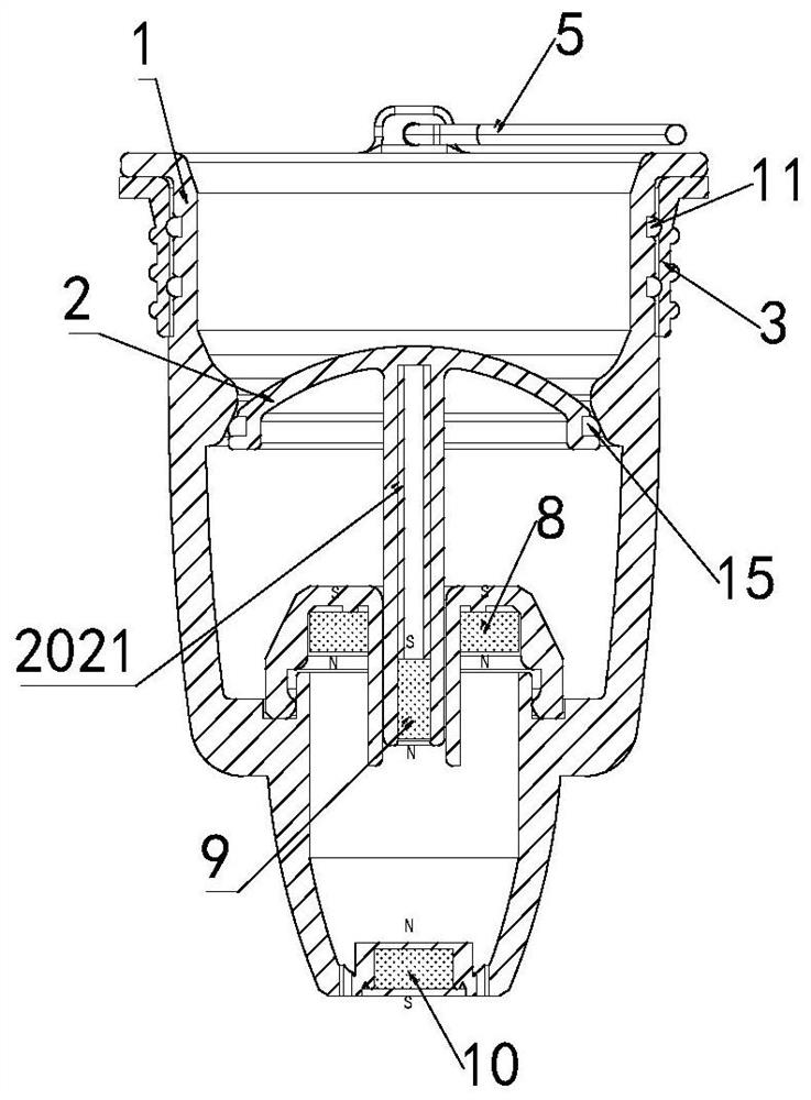
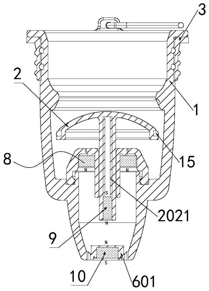
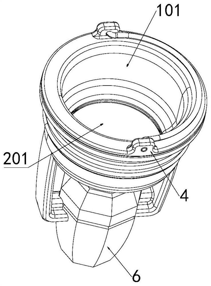
The invention discloses a magnetic type rapid drainage floor drain. The problems that the acting force between two magnets in an existing magnetic type floor drain is not balanced, so that the drainage distance is small, the drainage efficiency is low, and water is prone to being accumulated above the floor drain are solved. The magnetic type rapid drainage floor drain comprises a floor drain body, wherein a T-shaped valve and a sleeve shell are arranged at a water outlet of the floor drain body, the lower end of the T-shaped valve is inserted into the sleeve shell and abuts against a magnetic ring in the sleeve shell, a first magnetic column and a second magnetic column are fixed to the lower end of the magnetic ring at intervals, the same poles of the first magnetic column and the second magnetic column are opposite, and the opposite poles of the magnetic ring and the first magnetic column are opposite. The magnetic ring is additionally arranged in the original magnetic floor drain, the principle that the opposite poles of the magnetic ring and the first magnetic column attract each other and the same poles of the first magnetic column and the second magnetic column repel each other is utilized, so that the first magnetic column keeps the balance of the upper acting force and the lower acting force in a water passing state, the displacement distance of the T-shaped valve is increased to be twice of the original displacement distance, the drainage speed can be effectively increased, meanwhile, the water outlet is timely and perfectly sealed by a sealing cover after drainage is completed, and the deodorization effect is good.

Description

technical field [0001] The invention relates to the technical field of floor drains, in particular to a magnetic suction type fast drainage floor drain. Background technique [0002] The floor drain is an important interface connecting the drainage pipeline system with the indoor floor. The floor drain has the functions of drainage, preventing the odor in the drainage pipeline from being transmitted back to the room, anti-clogging, and easy cleaning. [0003] There is a common structure in the existing magnetic floor drain, which includes a floor drain body, a T-shaped valve is provided at the water outlet of the floor drain body, and two spaced apart magnets are fixed at the lower end of the T-shaped valve, wherein A magnet is in contact with the T-shaped valve, and the two magnets are arranged with the same pole facing each other. When the water is not flowing, the lower magnet gives an upward repulsion to the upper magnet, thereby making the T-shaped valve firmly seal the...

Claims


Application Information

Patent Timeline
IPC IPC(8): E03F5/04
CPCE03F5/0407E03F2005/0416
Inventor 邓华国
Owner YUHUAN YU GOVERNANCE PLUMBING CO LTD
Why Eureka
Try Eureka