Loader hood automatic tailor welding device

A loader and automatic technology, applied in auxiliary devices, welding equipment, auxiliary welding equipment, etc., can solve the problems of low utilization rate of the device, easy deviation of the position of the air-conditioning installation frame, single type of splicing, etc. Effect

Active Publication Date: 2021-11-26
山东明宇重工机械有限公司
View PDF1 Cites 2 Cited by
  • Summary
  • Abstract
  • Description
  • Claims
  • Application Information

AI Technical Summary

Problems solved by technology

[0004] (1) The device can only clamp a hood with a single shape. When it can only clamp a hood with a fixed angle between the left panel assembly and the right panel assembly, the splicing type is single, making the device Low utilization to accommodate design changes to more angles between left and right panel assemblies
[0005] (2) The position of the clamping assembly used to fix the locking feet cannot be adjusted, and the jig used to limit the locking feet cannot be changed, and cannot be adapted to different shapes of locking feet at any time
[0006] (3) The right support seat and the left support seat cannot adjust the hole positioning structure on the left side plate assembly and the right side plate assembly, and cannot adapt to the clamping of different types of hoods
[0007] (4) The device does not have components for clamping the air conditioner installation frame, and it is easy to deviate from the position of the air conditioner installation frame, which will affect the subsequent air conditioner installation
[0008] (5) The left panel assembly, top panel assembly, and right panel assembly are tailor-welded to form a semi-finished product with a U-shaped structure. This device can only tailor-weld the semi-finished product and the locking feet

Method used


Image

  • Loader hood automatic tailor welding device
  • Loader hood automatic tailor welding device
  • Loader hood automatic tailor welding device

Examples


Embodiment Construction

[0044] The present invention will be described in detail below, and the technical solutions in the embodiments of the present invention will be clearly and completely described. Apparently, the described embodiments are only some of the embodiments of the present invention, not all of them. Based on the embodiments of the present invention, all other embodiments obtained by persons of ordinary skill in the art without making creative efforts belong to the protection scope of the present invention.

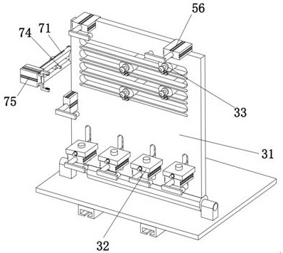
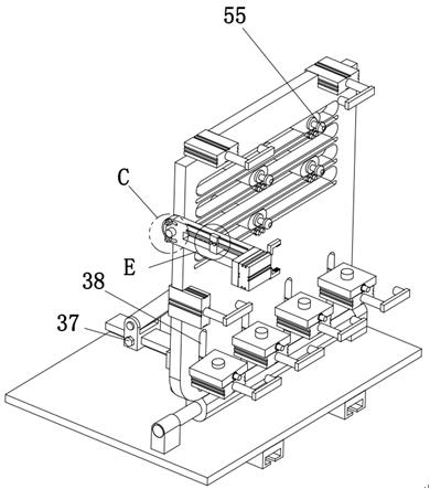
[0045] The present invention provides a loader hood automatic tailor welding device through improvement, such as Figure 1-Figure 17 As shown, there is an opposite tooling table 1, and the opposing tooling table 1 includes a working platform 11 with a rectangular structure, a slideway 17 horizontally installed on the working platform 11, and a two-way screw rod parallel to the centerline of the slideway 17 12. The two-way screw rod 12 is respectively provided with half-segment thre...


PUM


Abstract

The invention relates to the field of loader welding technology, in particular to an automatic tailor welding device for a loader hood, which includes an opposing tooling platform, and the opposing tooling platform includes a working platform, a slideway and a two-way screw rod, and the two-way From the midpoint to both ends of the screw rod, half threads with opposite helical directions are respectively provided. Two mobile platforms are slidably installed on the slideway, and an automatic tailor welding device is also included. The automatic tailor welding device includes two single A body tailor welding device, the single body tailor welding device includes a rotating shaft, a vertical plate, a locking foot adaptation clamping mechanism and a side plate adaptation clamping mechanism, and the back side of the vertical plate is hinged with a support rod. The present invention All fixtures can be adjusted in three degrees of freedom, and can be adapted to different structures of locking feet and positioned and welded at the bottom of the vertical plate. The angle of tailor welding on the two vertical plates can be adjusted, and it can be used for different types of left plate components and The positioning holes in different positions of the right side plate assembly are used for positioning.

Description

technical field [0001] The invention relates to the technical field of loader welding, in particular to an automatic tailor welding device for a loader hood. Background technique [0002] The hood is an important appearance part on the loader, and the hood is mostly a segmented structure, that is, the front, middle and rear hoods. Such as Figure 12 As shown, it is a schematic diagram of the loader hood of the present invention. The loader hood includes a left side panel assembly, a top panel assembly, a right side panel assembly, a right locking foot, an air conditioner mounting bracket and a left locking foot; the hood assembly is welded After completion, the three sections of the hood should be coordinated and beautiful as a whole after installation. Therefore, the hood tailor welding positioning device is an important link to ensure the accuracy of the overall forming position tolerance of the hood. The traditional tailor welding method is to use a simple tailor welding ...

Claims


Application Information

Patent Timeline
Patent Type & Authority Patents(China)
IPC IPC(8): B23K37/00B23K37/04
CPCB23K37/00B23K37/0443
Inventor 衣学航焦洪旭宋林峰陈洪庆王国皓
Owner 山东明宇重工机械有限公司
Why Eureka
Try Eureka