Cast-in-place pile head concrete stripping and chiseling device

A technology of concrete and cast-in-place piles, which is applied to sheet pile walls, buildings, and foundation structure engineering, etc., which can solve problems affecting construction progress and construction quality, long construction period, and irregular sectional surfaces, etc., and achieve good quality of overall stripping and chisel removal , good crushing, stripping and truncation, avoiding the effect of excessive truncation length

Active Publication Date: 2021-10-19
湖北远大建设集团有限公司
View PDF14 Cites 0 Cited by
  • Summary
  • Abstract
  • Description
  • Claims
  • Application Information

AI Technical Summary

Problems solved by technology

[0003] The purpose of the present invention is that the crushing and truncation of the existing concrete pile head is difficult. The traditional pile head concrete stripping and chiseling method is time-consuming, labor-intensive, and the construction period is long. Moreover, it is difficult to control the position of the broken section surface, which is extremely difficult. It is easy to lead to the situation that the cut-off length is too large or the cut-off length is insufficient. At the same time, the quality of the overall stripping chisel is not good, and the cut-off surface is irregular, which seriously affects the subsequent construction progress and construction quality. The construction only needs manual auxiliary operations, the construction efficiency has been greatly improved, and the position of the broken section can be precisely controlled, avoiding the situation of excessive or insufficient truncated length, and the overall stripping and chiseling quality is good, A concrete stripping and chiseling device for cast-in-situ pile heads that has a regular sectional surface and will not cause damage to the lower part of the concrete pile head

Method used


Image

  • Cast-in-place pile head concrete stripping and chiseling device
  • Cast-in-place pile head concrete stripping and chiseling device
  • Cast-in-place pile head concrete stripping and chiseling device

Examples


Embodiment Construction

[0026] The present invention will be further described in detail below in conjunction with the accompanying drawings and specific embodiments.

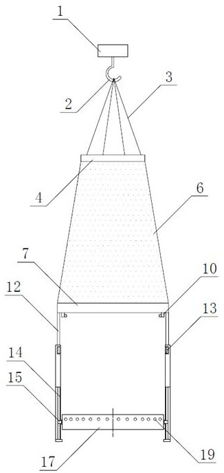
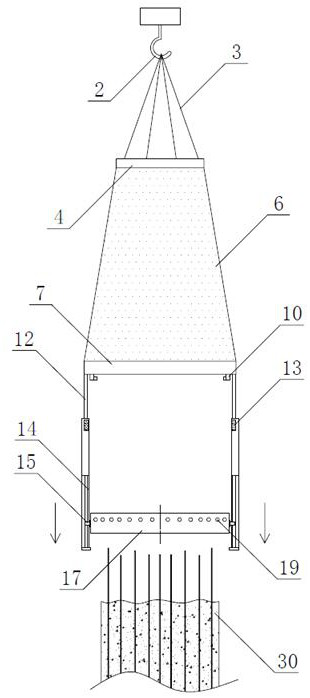
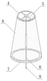
[0027] see Figure 1 to Figure 8 , a concrete stripping chisel removal device for a cast-in-place pile head of the present invention, comprising a hanger 1, a hanger 2, a wire rope 3 and a hanger ring 4, the lower end of the hanger 1 is equipped with a hanger 2, and the hanger 2 passes through the wire rope 3 It is connected with the hanging ring 4 located below, and it is characterized in that: the lower end of the hanging ring 4 is fixed to the small mouth end of the positioning cone 6, and the lower part of the large mouth end of the positioning cone 6 is fixed with a fixed ring 7, and the hanging A connector 5 is fixed in the ring of the ring 4, a vertical support rod 8 is fixed on the lower end of the connector 5 and positioned on the axis of the positioning cone 6, the bottom of the vertical support rod 8 is provided with a supp...


PUM


Abstract

The invention discloses a cast-in-place pile head concrete stripping and chiseling device. The cast-in-place pile head concrete stripping and chiseling device comprises a lifting appliance (1), a lifting hook (2), a steel wire rope (3) and a hanging ring (4), and is characterized in that the lower end of the hanging ring (4) is fixed to the small opening end of a positioning conical barrel (6), a fixing ring (7) is fixed to the lower portion of the large opening end of the positioning conical barrel (6), a connecting piece (5) is fixed in a ring body of the hanging ring (4), a vertical supporting rod (8) is fixed to the position, located on the axis of the positioning conical barrel (6), of the lower end of the connecting piece (5), the bottom of the fixing ring (7) is fixed to the upper end of a vertical fixing arm (12), a lifting mechanism is installed at the lower end of the vertical fixing arm (12), and the lifting connecting end of the lifting mechanism is fixedly connected with an annular outer frame (17). The device is reasonable in structure, mechanical automatic construction is adopted, the construction efficiency is greatly improved, the position of a broken cut-off plane can be accurately controlled, the overall stripping and chiseling quality is good, and the cut-off plane is regular.

Description

technical field [0001] The invention relates to a concrete stripping and chiseling device, in particular to a concrete stripping and chiseling device for a cast-in-place pile pile head, which belongs to the technical field of construction engineering equipment. Background technique [0002] Bored pile is a common pile type widely used in building foundation construction, and it is widely used in various foundation constructions such as industrial and civil buildings and bridges. In order to ensure the quality of the pile head concrete of the cast-in-place pile, the code stipulates that when the bored pile is constructed, the height of the cast-in-place pile should be 500 mm to 1000 mm higher than the design height. Concrete pile heads. It is difficult to break and cut off the concrete pile head. Because it is a concrete cast-in-place structure, there are criss-cross steel bars inside the concrete pile head, which is limited by the size of the space. At the same time, it can...

Claims


Application Information

Patent Timeline
Patent Type & Authority Applications(China)
IPC IPC(8): E02D9/00E02D5/34
CPCE02D9/00E02D5/34
Inventor 朱克冰王瑞丰普娜胡丽霞刘方曹力余浩
Owner 湖北远大建设集团有限公司
Why Eureka
Try Eureka