Large-drift-diameter dry type quick connector

A large-diameter, dry-type technology, applied in the direction of mechanical equipment, couplings, etc., can solve the problems of impurities affecting the sealing performance, the flow area becomes smaller, and the leakage point is increased, so as to achieve smooth internal circulation, improve the flow coefficient, reduce the The effect of overall flow resistance

Active Publication Date: 2021-09-17
SHANDONG INST OF AEROSPACE ELECTRONICS TECH
View PDF11 Cites 0 Cited by
  • Summary
  • Abstract
  • Description
  • Claims
  • Application Information

AI Technical Summary

Problems solved by technology

However, the inner spool of this quick connector has a conical surface structure, and the butt joint and separation seals are exposed in the flow channel, and impurities are easily enriched in the seals, thereby affecting the sealing performance; the conical spool makes the flow area smaller and the flow resistance increase
At the same time, the female joint housing provides a possible leak point for the two parts to be sealed by a seal

Method used


Image

  • Large-drift-diameter dry type quick connector
  • Large-drift-diameter dry type quick connector
  • Large-drift-diameter dry type quick connector

Examples


Embodiment 1

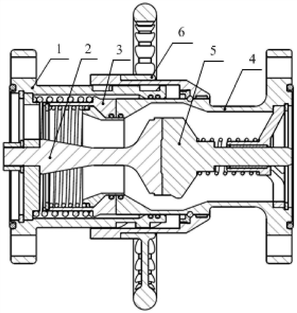
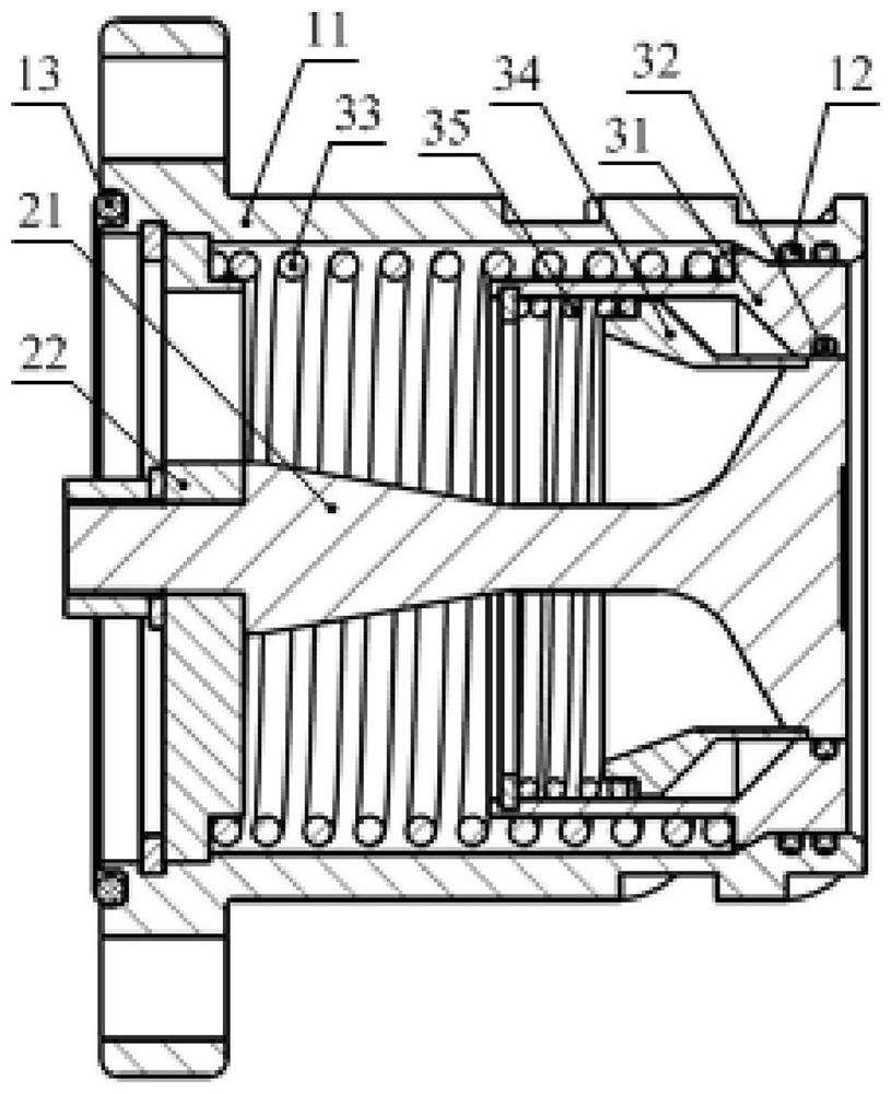
[0032] Such as Figure 1 to Figure 4 As shown, the present invention proposes a dry type quick joint with a large diameter, which includes a male joint (such as figure 2 ) and female connectors (such as image 3 ). Specifically, the male joint has a male joint housing assembly 1, a fixed valve core assembly 2, and a moving valve core assembly 3; the fixed valve core assembly 2 and the moving valve core assembly 3 form an the first channel of

[0033] The male joint housing assembly 1 includes the male joint housing 11, the male joint housing seal 12 and the outer seal 13 of the male joint; the outer housing 11 has a locking curved groove 111, and the inner cavity is provided with a fixed valve core assembly 2 and a movable The spool assembly 3; the fixed spool assembly 2 includes a fixed spool 21 and a fixed spool seat 22, and the rear part is fixed by a retaining ring; the movable spool assembly 3 includes a first movable spool 31, a first movable spool seal 32, the firs...

Embodiment 2

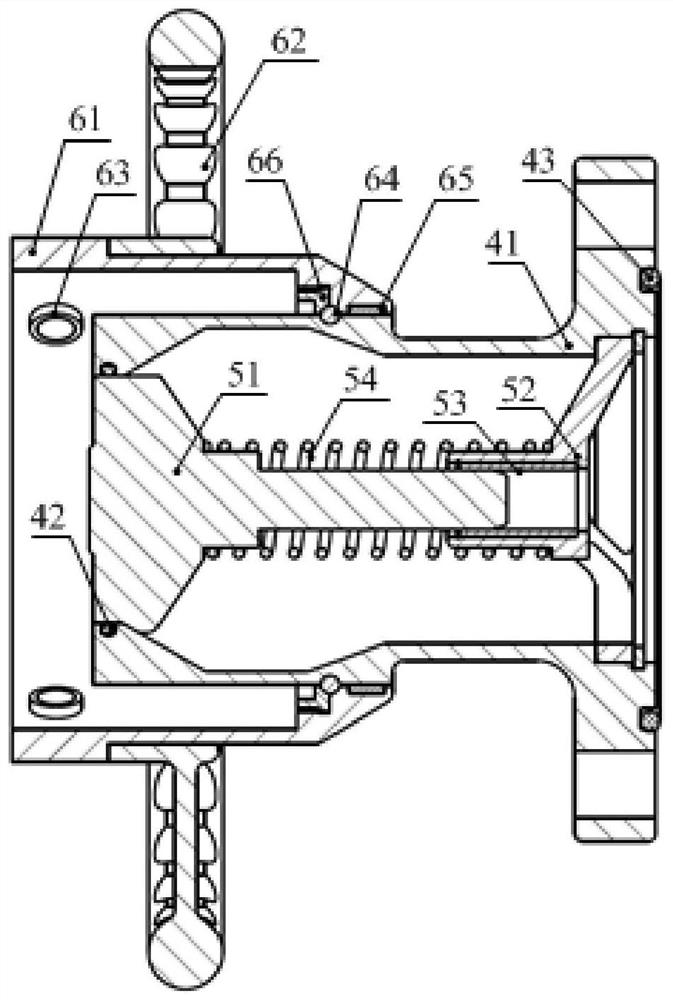
[0041] Such as Figure 1 to Figure 4 As shown, the male joint and the female joint rely on the sliding of the locking roller 63 on the female joint locking assembly 6 in the curved groove 111 on the male joint housing 11 to achieve docking and locking; the female joint locking assembly 6 passes through a set of circumferential steel Ball 64, guide ring 65 and steel ball fixing ring 66 realize the smooth rotation of operating hand wheel 62; guide ring 65 completes the circumferential direction support of the locking assembly, and steel ball fixing ring 66 compresses steel ball 64 in the circular groove to prevent steel ball The ball 64 comes out;

[0042] Other structures are the same as those in Embodiment 1, and will not be repeated here.

Embodiment 3

[0044] Such as Figure 4 As shown, the male connector housing 11 is provided with a male connector housing locking curved groove 111 for locking the male connector and the female connector, which is used to constrain the movement track of the locking roller 63 and realize the docking of the male connector and the female connector; the male connector The locking curve groove 111 of the joint housing is a multi-segment curve, and the curve can be expanded into a horizontal line segment, a multi-segment obliquely downward straight line segment, a multi-segment obliquely upward straight line segment and a vertical line segment, or other types of curve segments in the same direction;

[0045] Other structures are the same as those in Embodiment 1, and will not be repeated here.


PUM


Abstract

The invention relates to the technical field of fluid pipeline connection, in particular to a large-drift-diameter dry type quick connector which comprises a male connector and a female connector matched with each other. The male connector comprises a male connector shell assembly, a male connector fixed valve element assembly and a male connector movable valve element assembly. The female connector comprises a female connector shell assembly, a female connector valve element assembly and a female connector locking assembly. The fluid pipeline connecting device adopts a butt joint mode of quickly locking a flat head structure and a roller curved groove, so that accurate and rapid butt joint is realized on the premise of respective sealing performance of a male joint and a female joint, and therefore, a fluid can effectively circulate in a flow channel set between the butt joint structures; thus, the design purposes of simplifying butt joint and unlocking operation, avoiding fluid leakage, improving the flow coefficient and improving the impurity resistance and the field operation efficiency are achieved. The large-drift-diameter dry type quick connector is reasonable in design, high in sealing performance and smaller in internal fluid resistance, and all the internal sealing pieces do not make contact with flowing working media all the time.

Description

technical field [0001] The invention relates to the technical field of fluid pipeline connection, in particular to a large-diameter dry quick connector. Background technique [0002] In a large flow fluid transmission system, in order to assemble, debug and maintain the system, it is often necessary to connect and disconnect the fluid. The joint devices in the prior art often add cut-off valves at both ends of the male joint and the female joint. The joints are only responsible for communication and sealing, and then the connection and disconnection of the fluid are controlled by operating the valve. This method not only increases the number, volume and cost of the equipment, but also has a certain amount of media leakage during the connection and disconnection process, especially for toxic, harmful, high-risk and precious fluid media, which will pollute the environment and waste materials. Operators have greater potential safety hazards. On the other hand, due to the exis...

Claims


Application Information

Patent Timeline
IPC IPC(8): F16L37/32F16L37/23
CPCF16L37/32F16L37/23
Inventor 张龙王文正高青李文波马俊太王义达吕明帅夏辉倪森
Owner SHANDONG INST OF AEROSPACE ELECTRONICS TECH
Why Eureka
Try Eureka