Coil stock butt joint device, coil stock machining equipment and coil stock butt joint method

A docking device and roll material technology, which is applied in the directions of winding strips, thin material handling, transportation and packaging, etc., can solve problems such as low efficiency and error-prone

Pending Publication Date: 2020-09-29
GUANGDONG JATEN ROBOT & AUTOMATION
View PDF0 Cites 0 Cited by
  • Summary
  • Abstract
  • Description
  • Claims
  • Application Information

AI Technical Summary

Problems solved by technology

[0002] With the development of intelligent manufacturing, manual and semi-automatic material handling methods are being replaced by fully automatic equipment. In the original manual and semi-automatic material handling methods, if the positioning is not accurate during the material docking process, secondary or multiple adjustments can be made. To ensure the smooth docking of materials, however, this docking method is too inefficient and error-prone

Method used


Image

  • Coil stock butt joint device, coil stock machining equipment and coil stock butt joint method
  • Coil stock butt joint device, coil stock machining equipment and coil stock butt joint method
  • Coil stock butt joint device, coil stock machining equipment and coil stock butt joint method

Examples


no. 1 example

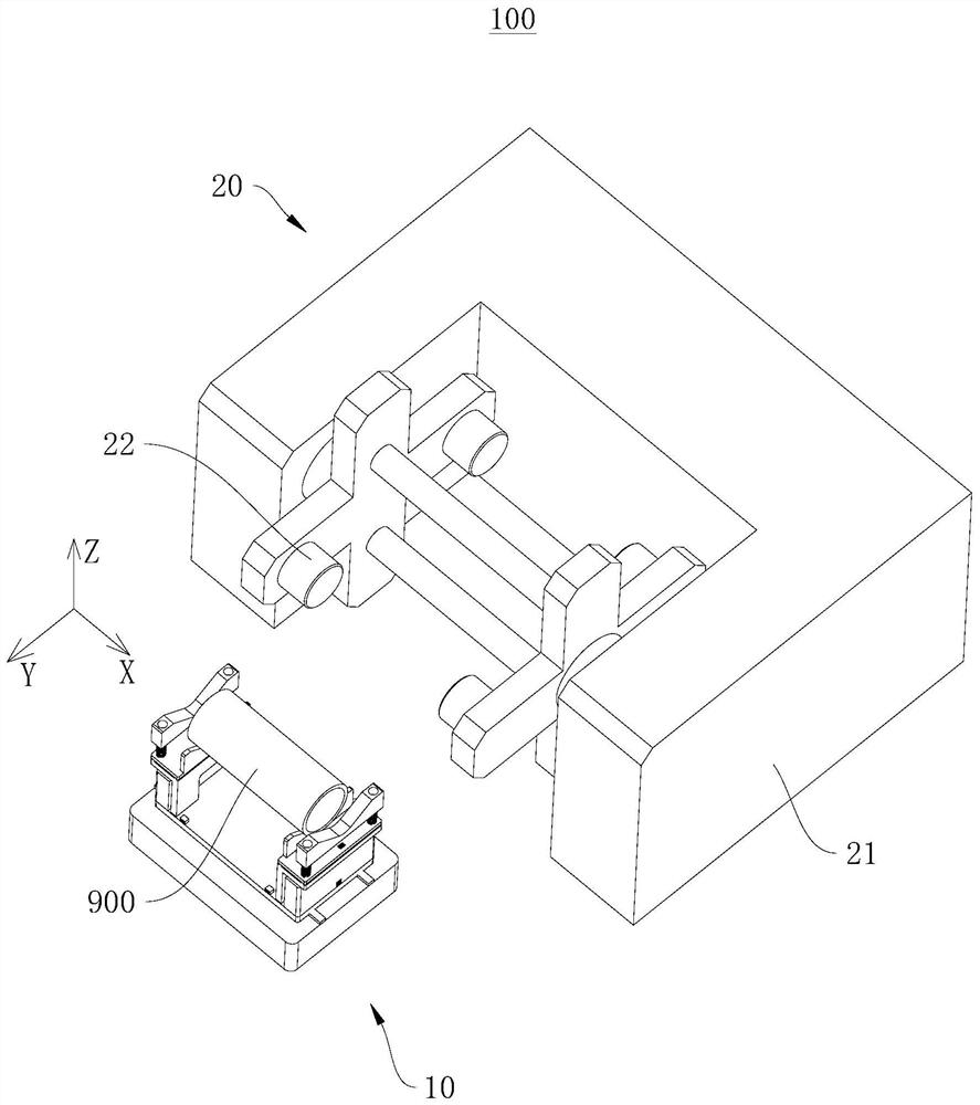
[0037] see figure 1 , figure 1 It is a structural schematic diagram of the coil material docking device 10 applied to the coil material processing equipment 100 provided by the first embodiment of the present invention. exist figure 1 Among them, the direction indicated by the X arrow is the third direction X, the direction indicated by the Y arrow is the second direction Y, and the direction indicated by the Z arrow is the first direction Z.

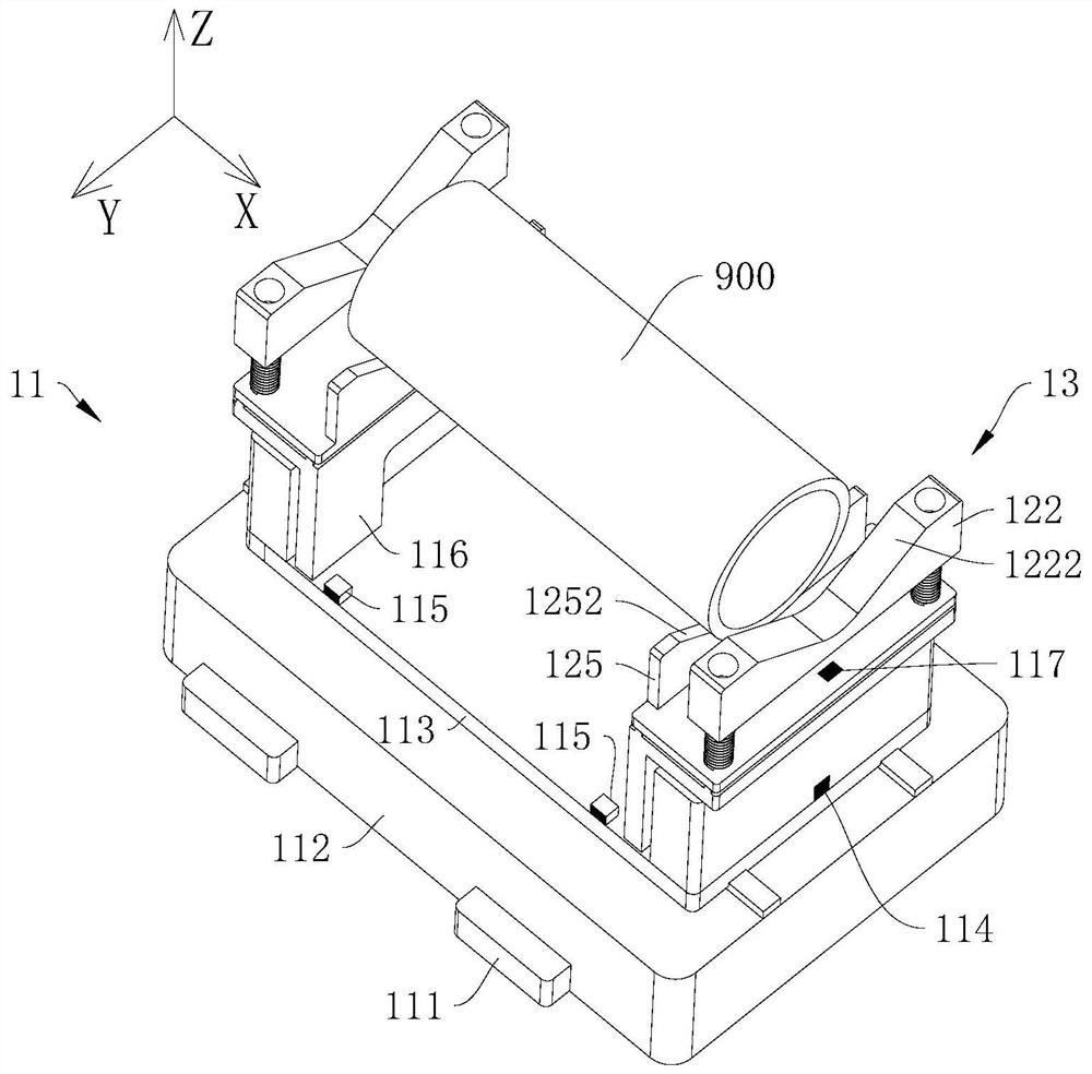
[0038] The first embodiment of the present invention provides a coil material docking device 10, which has the characteristics of precise docking and high docking efficiency. The coil butt joint device 10 can be applied to a coil material processing equipment 100 or a coil material production line, etc. Of course, the coil material butt joint device 10 can also be used independently.

[0039] Wherein, taking the coil material docking device 10 applied to the coil material processing equipment 100 as an example, the coil material proc...

no. 2 example

[0084] see Figure 7 , Figure 7 It is a schematic flow chart of the coil butt jointing method provided by the second embodiment of the present invention.

[0085] The second embodiment of the present invention provides a coil material docking method, which also has the characteristics of precise docking and high docking efficiency. The coil butt joint method can be applied to the coil butt joint device 10 in the above-mentioned embodiment.

[0086] It should be noted that the basic principles and technical effects of the coil material docking method provided in this embodiment are the same as those of the above-mentioned embodiment. For a brief description, the part not mentioned in this embodiment can refer to the above-mentioned embodiment corresponding content.

[0087] The coil docking method includes:

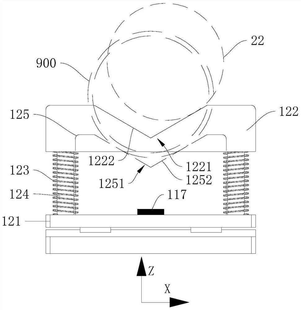
[0088] Step S101: move the carrying mechanism 13 to the bottom of the coil shaft 22, and make the docking gap 1221 correspond to the coil shaft 22;

[0089] Step S10...


PUM


Abstract

The invention discloses a coil stock butt joint device, coil stock machining equipment and a coil stock butt joint method, and relates to the technical field of cargo carrying butt joint. The coil stock butt joint device comprises a moving mechanism and a bearing mechanism, the moving mechanism can drive the bearing mechanism to move to the position below a coil stock shaft of the coil stock machine so that a butt joint notch can correspond to the coil stock shaft, and the moving mechanism can further drive the bearing mechanism to vertically rise the butt joint distance in the first directionso that to-be-moved coil stocks on the bearing notch can be coaxial with the coil stock shaft, or the peripheral surface of the to-be-moved coil stock on the coil stock shaft abuts against the two side walls of the bearing notch, and when the bearing mechanism ascends and the coil stock shaft abuts against the side wall of the butt joint notch, the bearing mechanism can move along the straight line where the second direction is located under the abutting effect of the coil stock shaft, so that the butt joint notch corresponds to the coil stock shaft. The coil stock butt joint device, the coilstock machining equipment and the coil stock butt joint method have the advantages of being accurate in butt joint and high in butt joint efficiency.

Description

technical field [0001] The invention relates to the technical field of cargo handling and docking, in particular to a coil material docking device, coil material processing equipment and a coil material docking method. Background technique [0002] With the development of intelligent manufacturing, manual and semi-automatic material handling methods are being replaced by fully automatic equipment. In the original manual and semi-automatic material handling methods, if the positioning is not accurate during the material docking process, secondary or multiple adjustments can be made. To ensure the smooth docking of materials, however, this docking method is too inefficient and error-prone. [0003] In view of this, it is particularly important to develop and design a coil material butt joint device, coil material processing equipment and coil material butt joint method that can solve the above technical problems. Contents of the invention [0004] The object of the present ...

Claims


Application Information

Patent Timeline
Patent Type & Authority Applications(China)
IPC IPC(8): B65H19/30
CPCB65H19/30
Inventor 黎扬福苏毅宾李廷禧
Owner GUANGDONG JATEN ROBOT & AUTOMATION
Why Eureka
Try Eureka