Aviation refueling connector lifting device

A technology for refueling joints and aviation, applied in the direction of liquid conveying devices, etc., can solve the problems of increasing the difficulty of the operator's work, unable to carry out wide-scale promotion and application, and shortening the service life of gas springs.

Pending Publication Date: 2020-04-21
CHONGQING ENDURANCE IND +1
View PDF0 Cites 0 Cited by
  • Summary
  • Abstract
  • Description
  • Claims
  • Application Information

AI Technical Summary

Problems solved by technology

[0003] At present, most of the larger airports use the ground well pipe network refueling mode. When refueling, a refueling joint that connects the ground well pipe network interface with the aircraft refueling port is needed. At present, most airports use manual handling of the refueling joint. Firstly, the refueling joint is transported to the refueling interface of the underground well pipe network through mechanical equipment, and then the refueling joint is moved by manpower and the position of the refueling joint is adjusted up and down, so that the refueling joint can be connected with the refueling interface of the underground well pipe network. The refueling joint facilities used are heavy, and currently only rely on manpower to move and adjust the position of the refueling joint. The biggest hidden danger of this method is that the personal safety of the workers cannot be guaranteed. In addition, this method is due to manual handling and adjustment of the refueling joint. position, so that the refueling connector is connected to the refueling connector in the ground well pipe network, which makes the efficiency of refueling the aircraft even lower
[0004] At present, gas springs are used to lift the refueling connector, and then the refueling connector is lifted. The basic principle is to drive the refueling connector to move vertically through the expansion and contraction of the gas spring, but this method cannot be well realized. The main reasons f

Method used


Image

  • Aviation refueling connector lifting device
  • Aviation refueling connector lifting device
  • Aviation refueling connector lifting device

Examples


Embodiment Construction

[0020] The technical solutions in the present invention will be further described below in conjunction with the accompanying drawings and embodiments.

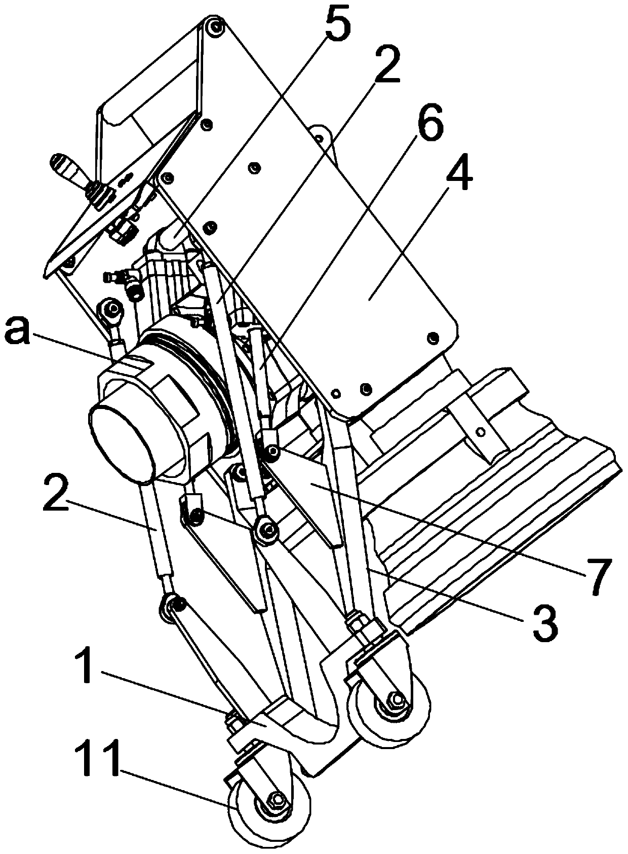
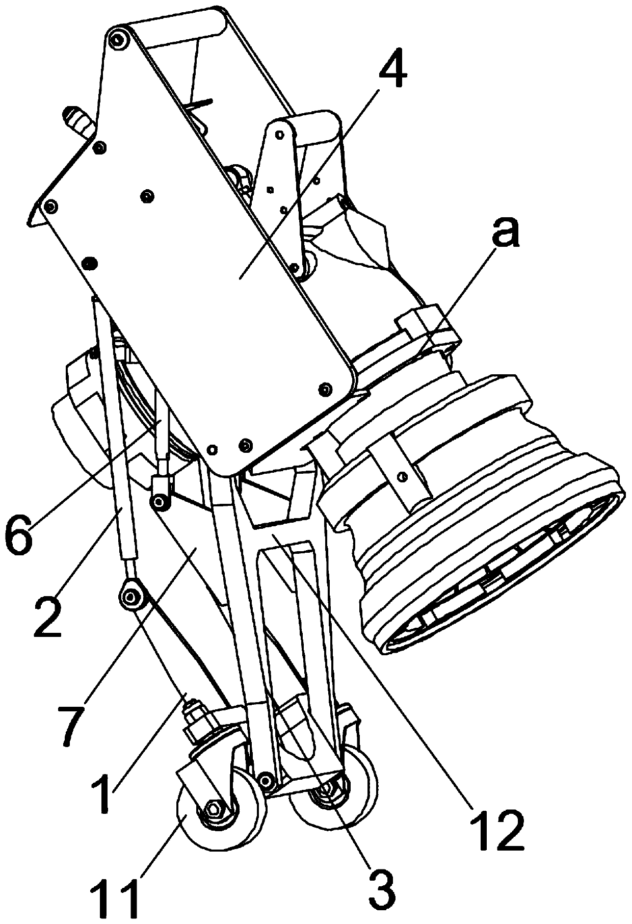
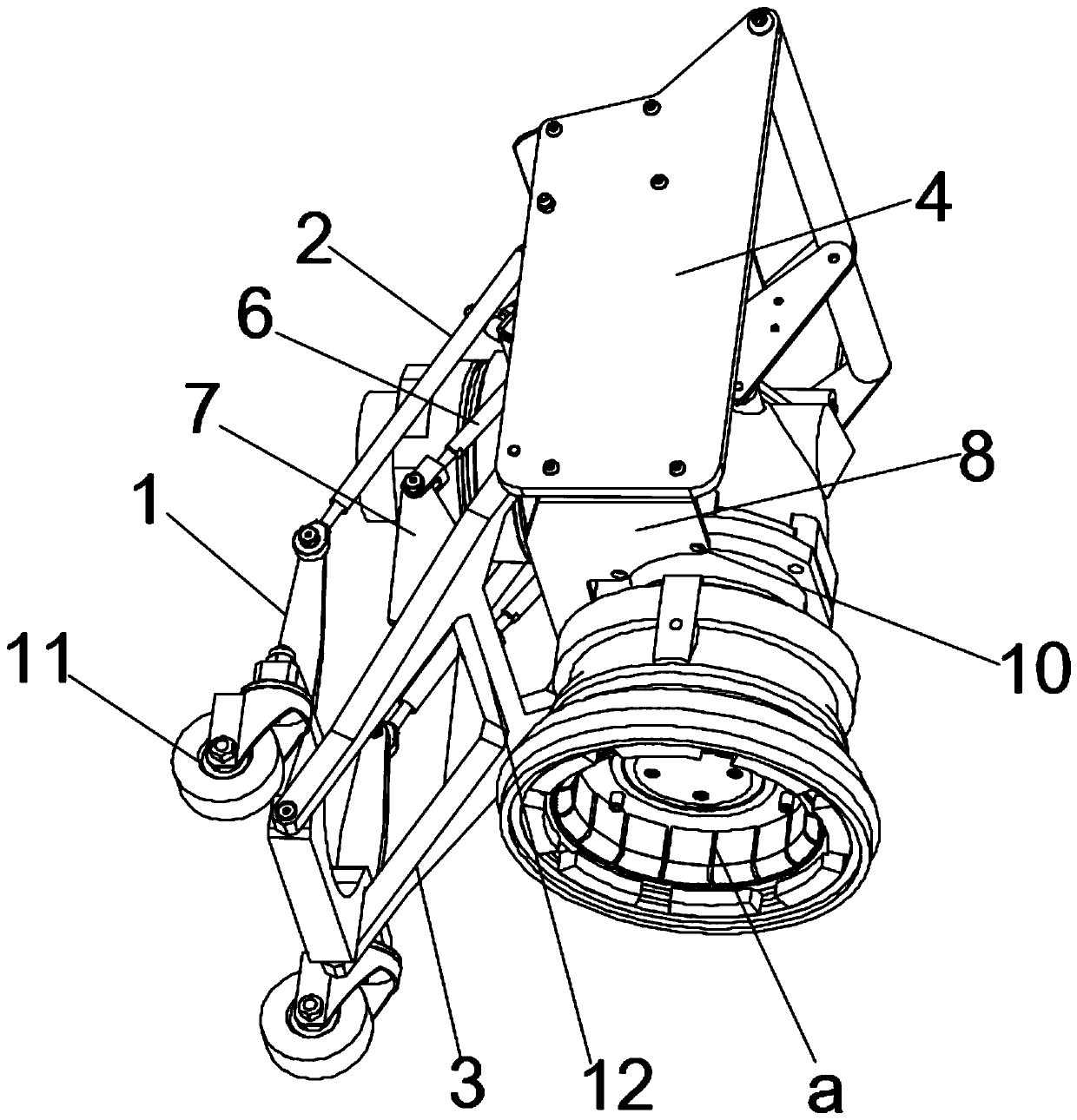
[0021] Such as figure 1 and figure 2 As shown, an aviation refueling joint lifting device includes a bracket 1, two parallel upper connecting rods 2, two parallel lower connecting rods 3, a detachable mounting shell 4 for installing the refueling joint a and a drive assembly, two The upper connecting rods 2 are all located on the top of the bracket 1 and one end of the two upper connecting rods 2 is hinged with the bracket 1, and the other ends of the two upper connecting rods 2 are hinged on the upper part of the mounting shell 4, and the two lower connecting rods 3 are all hinged. It is located at the lower part of the bracket 1 and one end of the two lower connecting rods 3 is hinged with the bracket 1, and the other ends of the two lower connecting rods 3 are hinged at the lower part of the installation shell 4, and the ...


PUM


Abstract

The invention discloses an aviation refueling connector lifting device which is used for solving the technical problem of how to conveniently and flexibly achieve precise butt joint of a refueling connector and a ground well pipe network refueling connector mentioned in the background technology. The aviation refueling connector lifting device comprises a bracket, parallel upper connecting rods, parallel lower connecting rods, a mounting shell for detachably mounting an oiling joint, and a driving assembly, one end of each upper connecting rod is hinged with the upper part of the bracket; theother ends of the upper connecting rods are hinged to the upper part of the mounting shell; the lower connecting rods are positioned at the same horizontal position; one ends of the lower connecting rods are hinged with the lower part of the bracket; the other ends of the lower connecting rods are hinged at the lower portion of the mounting shell; and the driving assembly is arranged between the bracket and the mounting shell and used for driving the upper connecting rods and the lower connecting rods to rotate so as to drive the mounting shell to move up and down and be locked, and the aviation refueling connector lifting device is convenient to operate and mainly used for refueling an aircraft.

Description

technical field [0001] The invention relates to the technical field of aircraft refueling, in particular to an aviation refueling joint lifting device for conveniently lifting a refueling joint in a well pipe network. Background technique [0002] With the rapid development of science and technology and economy, my country's transportation facilities have been greatly improved. In recent years, my country has built more airports and equipped with more air flights, which makes people's travel more convenient and faster. , and the increase of some international flights also provides a more solid foundation for our country to strengthen international cooperation. [0003] At present, most of the larger airports use the ground well pipe network refueling mode. When refueling, a refueling joint that connects the ground well pipe network interface with the aircraft refueling port is needed. At present, most airports use manual handling of the refueling joint. Firstly, the refuelin...

Claims


Application Information

Patent Timeline
IPC IPC(8): B64F1/28
CPCB64F1/28
Inventor 李津泽石静敖千涂汉炯
Owner CHONGQING ENDURANCE IND
Why Eureka
Try Eureka