Backlight module and liquid crystal display of backlight module

A backlight module, optical technology, applied in the direction of instruments, optics, light guides, etc., can solve the problems of insufficient space, falling off of the optical film group, limited distance between the edge of the optical film group and the support plate, etc., to save production costs, application wide range of effects

Inactive Publication Date: 2013-01-09
TCL CHINA STAR OPTOELECTRONICS TECH CO LTD
View PDF4 Cites 16 Cited by
  • Summary
  • Abstract
  • Description
  • Claims
  • Application Information

AI Technical Summary

Problems solved by technology

Then, in the above-mentioned existing liquid crystal display device, the platform is only supported by the support plate, and the distance between the edge of the optical film group and the support plate is limited, when the optical film group is under the heat from the light source, especially when receiving During high-temperature testing, it is easy to expand due to heat and cause insufficient space, resulting in waving deformation, affecting the picture effect of the liquid crystal display device, and even causing the optical film group to fall off

Method used


Image

  • Backlight module and liquid crystal display of backlight module
  • Backlight module and liquid crystal display of backlight module
  • Backlight module and liquid crystal display of backlight module

Examples


Embodiment Construction

[0032] Preferred embodiments of the present invention will be described below with reference to the accompanying drawings.

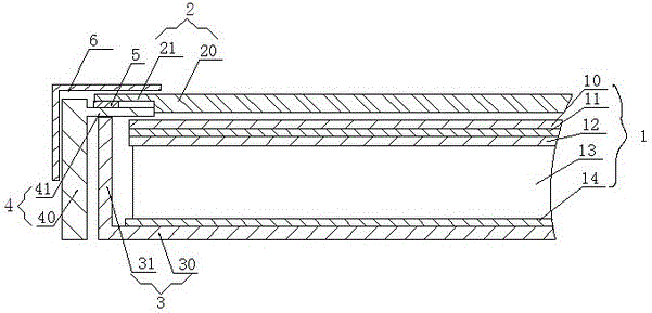
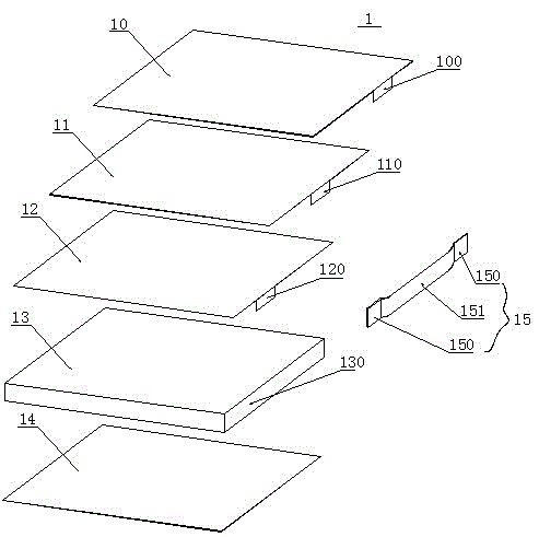
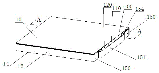
[0033] Please combine Figure 2 to Figure 4 As shown, a backlight module according to an embodiment of the present invention is shown. It can be seen that the backlight module 1 includes:

[0034] The light guide plate 13 is provided with a light incident surface and a light exit surface, and a light source is provided on the side of the light incident surface. In this embodiment, the light incident surface is arranged on one side of the light guide plate 13, and the light exit surface is the the top surface;

[0035] The optical film group is located above the light guide plate 13, facing the light exit surface of the light guide plate 13, and at least one side of at least one optical film in the optical film group extends with a foldable portion. Specifically, the The optical film set includes a first diffuser plate 10, a prism plate 11, and a secon...


PUM


Abstract

The embodiment of the invention discloses a backlight module, which comprises a light guide plate, an optical film group and at least one positioning device, wherein the light guide plate is provided with a light inlet surface and a light outlet surface, a light source is arranged at the light inlet surface, the optical film group is arranged above the light guide plate and is opposite against the light outlet surface of the light guide plate, a foldable part extends from at least one side edge of at least one optical film of the optical film group, the positioning device is arranged at least one side surface of the light guide plate, except the light inlet surface, an accommodating space is formed between the positioning device and the side surface of the light guide plate, and the foldable part of the optical film is folded and is then accommodated into the accommodating space. The embodiment of the invention correspondingly provides a liquid crystal display adopting the backlight module. According to the embodiment of the invention, the positioning of each optical film of the optical film group is simple, the wave-shaped deformation of the optical film caused by heat expansion or cold shrinkage can be prevented, in addition, the application is wide, and the production cost is saved.

Description

technical field [0001] The invention relates to a thin film transistor liquid crystal display (Thin Film Transistor Liquid Crystal Display, TFT-LCD) technology, in particular to a backlight module and a liquid crystal display thereof. Background technique [0002] TFT-LCD has become a very important display platform in modern information technology and video products. Such as figure 1 As shown, a cross-sectional view of a liquid crystal display module is shown. The liquid crystal display module includes a liquid crystal display panel 2, a backlight module 1 and a supporting device. Wherein, the backlight module 1 is arranged behind the liquid crystal display panel to provide light to the liquid crystal display panel; the supporting device is used to support and fix the liquid crystal display panel and the backlight module. The support device includes a back plate 3, a plastic frame 1, and an annular glass plate 5 covering the plastic frame, so that the liquid crystal disp...

Claims


Application Information

Patent Timeline
Patent Type & Authority Applications(China)
IPC IPC(8): F21S8/00F21V17/10G02F1/13357
CPCG02B6/0088G02F1/133606G02F1/133615G02F2201/54
Inventor 王甲强俞刚
Owner TCL CHINA STAR OPTOELECTRONICS TECH CO LTD
Why Eureka
Try Eureka