
Magnetic type intelligent mirror surface cabinet

A technology of magnetic suction and mirror cabinets, which is applied in the field of smart mirror cabinets, can solve the problems of reducing the sense of technology and style of smart mirror cabinets, potential safety hazards, and unsightly structures, so as to achieve a good sense of technology and appearance, and improve the decoration style. The effect of stable installation

Pending Publication Date: 2021-10-22
安徽省联晟智能科技有限公司
View PDF0 Cites 0 Cited by
  • Summary
  • Abstract
  • Description
  • Claims
  • Application Information

AI Technical Summary

Problems solved by technology

[0003] In the prior art, the glass mirror is usually installed by surface sticking, embedded clamping or inner side. Because of the existence of electronic components such as circuit boards on the rear side of the smart mirror, both surface sticking and embedded clamping are difficult. It is not suitable for the installation of smart mirror cabinets. These two installation methods have high requirements for dimensional accuracy and installation stability during installation, and the fixed installation method on the inner side will expose electronic components such as circuit boards to the rear of the cabinet panel, which may cause At the same time as a safety hazard, it is also unsightly in structure, which reduces the sense of technology and style of the smart mirror cabinet

Method used


Image

  • Magnetic type intelligent mirror surface cabinet
  • Magnetic type intelligent mirror surface cabinet
  • Magnetic type intelligent mirror surface cabinet

Examples


Embodiment Construction

[0018] The content of the present invention will be described below in conjunction with specific embodiments.

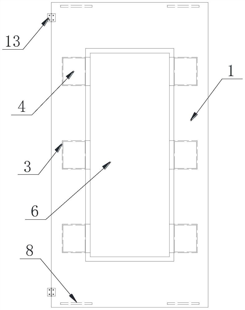
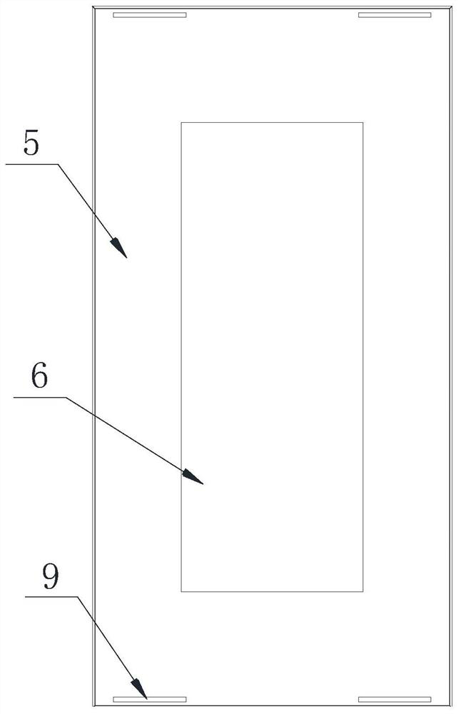
[0019] Such as Figure 1~4 As shown, the magnetic suction type smart mirror cabinet includes a cabinet panel 1 and a smart mirror 2, the smart mirror 2 is installed on the cabinet panel 1, and the front side of the cabinet panel 1 is provided with evenly distributed installation grooves 3. There is a fixed magnet 4 in the installation cavity 3, and a sheet metal back plate 5 is provided on the back side of the smart mirror 2. The sheet metal back plate 5 is a groove-shaped metal plate, and the sheet metal back plate 5 covers the smart mirror. 2 The back side and the outer edge, the sheet metal back plate 5 is magnetically fixed on the front surface of the cabinet panel 1, the middle part of the cabinet panel 1 and the sheet metal back plate 5 is provided with a through groove 6, and the installation groove 3 is located on the cabinet panel 1 In the interlayer on bot...


PUM


Abstract

A magnetic type intelligent mirror surface cabinet comprises a cabinet panel and an intelligent mirror surface, the intelligent mirror surface is mounted on the cabinet panel, mounting groove cavities which are evenly distributed are formed in the front side face of the cabinet panel, magnets which are fixedly mounted are arranged in the mounting groove cavities, a metal plate back plate is arranged on the back side of the intelligent mirror surface, and the metal plate back plate is a groove-shaped metal plate. The metal plate back plate covers the back side and the outer edge of the intelligent mirror surface, the metal plate back plate is fixed on the surface of the front side of the cabinet panel in a magnetic attraction mode, through grooves are formed in the middle of the cabinet panel and the middle of the metal plate back plate, the mounting groove cavities are located in interlayers on the two sides of the through groove of the cabinet panel, and a circuit control board of the intelligent mirror surface is arranged in the through groove of the metal plate back plate. And the circuit control board is mounted in the through groove of the cabinet panel in an embedded manner. During combined installation, the metal plate back plate is strongly attracted to the surface of the cabinet panel through the magnets, the installation mode of the intelligent mirror surface is simplified, the installation efficiency of the intelligent mirror surface cabinet is improved while the installation precision and stability are guaranteed, and the intelligent mirror surface cabinet is stable in overall structure, good in decoration impression and rich in technological aesthetic feeling.

Description

technical field [0001] The invention belongs to the field of intelligent mirror cabinets, in particular to a magnetic suction type intelligent mirror cabinet. Background technique [0002] The mirror cabinet is an indispensable article in daily life. It has the functions of decoration, storage and grooming. It is widely used in various occasions and is deeply loved by people. The mirror cabinet is mainly composed of a cabinet body and a glass mirror installed on the front side of the cabinet. With the development of science and technology, a control circuit board and corresponding networking embedding are added to the mirror cabinet, so that the glass mirror of the mirror cabinet can provide lighting, APP small Functions such as program query reminder and Internet surfing are more technologically oriented, satisfying the basic functions of the mirror cabinet and improving the decorative style of the mirror cabinet. [0003] In the prior art, the glass mirror is usually inst...

Claims


Application Information

Patent Timeline
IPC IPC(8): A47K1/02A47K1/08
CPCA47K1/02A47K1/08
Inventor 王杰
Owner 安徽省联晟智能科技有限公司
Learn More