Component pin tin plating equipment for electronic product production

A technology for electronic products and tin-plating equipment, applied in metal material coating process, coating and other directions, can solve problems such as cumbersome operation, and achieve the effect of improving work efficiency, avoiding movement, and having a high degree of automation

Pending Publication Date: 2021-10-22
深圳市海天恒和科技有限公司
View PDF5 Cites 0 Cited by
  • Summary
  • Abstract
  • Description
  • Claims
  • Application Information

AI Technical Summary

Problems solved by technology

[0004] In order to overcome the disadvantages of manually clamping the electrical components and then heating and melting the tin to form tin water when tinning the electrical components manually, the technical problem is to provide a Functional electronic product production with tinning equipment for component pins

Method used


Image

  • Component pin tin plating equipment for electronic product production
  • Component pin tin plating equipment for electronic product production
  • Component pin tin plating equipment for electronic product production

Examples


Embodiment 1

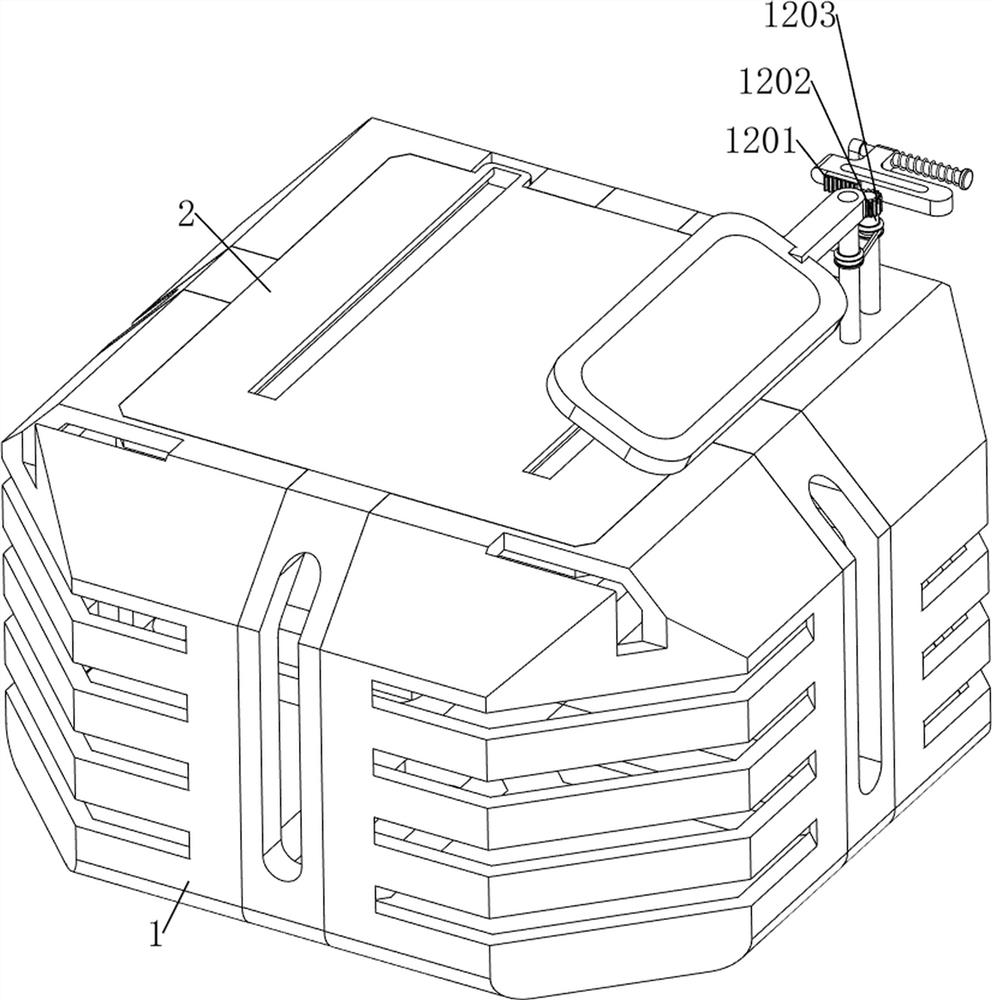
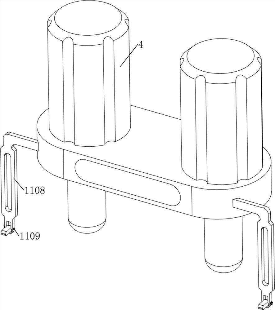
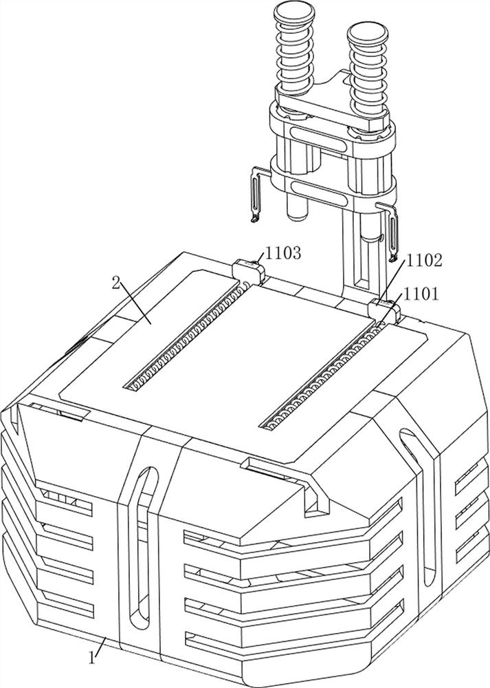
[0093] A tinning equipment for component pins used in the production of electronic products, such as Figure 1-Figure 7 As shown, it includes a casing 1, a first fixed plate 2, a first support plate 3, a tinning gun 4, a first movable rod 5, a first spring 6, a moving mechanism 7, a rotating mechanism 8 and a limit mechanism 9, the casing 1 There is a first fixed plate 2 in the middle of the top, a first support plate 3 is provided on the upper rear side of the housing 1, a first movable rod 5 is provided on the front side of the upper part of the first support plate 3, and the first movable rod 5 is symmetrically slid left and right, and the bottom of the first movable rod 5 Both are equipped with tinning guns 4, first springs 6 are arranged between the upper part of the first movable rod 5 and the first support plate 3, a moving mechanism 7 is provided on the upper right side of the inner rear part of the shell 1, and the lower part of the first support plate 3 A rotation me...

Embodiment 2

[0099] On the basis of Example 1, such as figure 1 , Figure 8 , Figure 9 , Figure 10 , Figure 11 , Figure 12 , Figure 13 , Figure 14 , Figure 15 and Figure 16 Shown, also comprise fixed mechanism 10, fixed mechanism 10 comprises the 6th support plate 101, inclined block 102, second fixed plate 103, guide bar 104, second spring 105, first movable plate 106, fixed bar 107, The first torsion spring 108, the first rotating plate 109, the limit rod 1010, the pressing plate 1011, the third spring 1012, the second fixed block 1013 and the second movable plate 1014, the second support plate 73 upper right side is provided with the sixth support plate 101, the front side of the sixth support plate 101 is provided with an inclined block 102, the upper right part of the rear side of the housing 1 is provided with a second fixed plate 103, and the upper right part of the second fixed plate 103 is provided with a guide rod 104, and the guide rod 104 is of sliding type A f...


PUM


Abstract

The invention relates to tin plating equipment, in particular to component pin tin plating equipment for electronic product production. The invention aims at providing the component pin tin plating equipment for electronic product production, which can automatically heat and melt tin and has a clamping function. The component pin tin plating equipment for electronic product production comprises a shell and a first fixing plate, wherein the first fixing plate is installed in the middle of the top of the shell; a first supporting plate installed on the upper portion of one side of the shell; and a first movable rod. According to the component pin tin plating equipment, a motor serves as driving force, under the cooperation of a missing gear and a first rack, a tin plating gun can be driven to move up and down, so that a tin wire is melted by the tin plating gun, the melted tin wire can fall onto a pin of a component, the tin plating operation is completed, then the remaining tin wire is pulled out forwards through rotation of a limiting block, next tin plating is facilitated, and the automation degree is relatively high, so that the working efficiency is improved.

Description

technical field [0001] The invention relates to tinning equipment, in particular to a tinning equipment for component pins used in the production of electronic products. Background technique [0002] Electronic products are related products based on electric energy. In the production process of electrical components, tinning is usually done on the pins of electrical components to enhance the corrosion resistance of the pins of electrical components, and at the same time enhance the corrosion resistance of the pins of electrical components. Solderability. [0003] The pins of existing electrical components need to be manually clamped with clips to the electrical components that need to be tinned, and then the tin is heated and melted to form tin water, and then the pins of the electrical components are put into tin water for tinning work. When the number of tin-plated electrical components is large, the manual operation is cumbersome, resulting in low work efficiency and hig...

Claims


Application Information

Patent Timeline
Patent Type & Authority Applications(China)
IPC IPC(8): C23C26/02
CPCC23C26/02
Inventor 练勉芳
Owner 深圳市海天恒和科技有限公司
Why Eureka
Try Eureka