Stress testing equipment for mechanical and electrical accessories
A technology of stress testing and accessories, applied in the direction of force/torque/power measuring instruments, measuring devices, instruments, etc., can solve the problems of inconvenient washing of electronic components and inconvenient cleaning of colloids, so as to avoid repeated pressing and debugging, and avoid the inconvenience of blocking The effect of cleaning up and reducing dependencies
- Summary
- Abstract
- Description
- Claims
- Application Information
AI Technical Summary
Problems solved by technology
Method used
Image
Examples
Embodiment 1
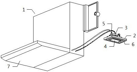
[0033] see figure 1, a stress testing device for mechanical and electrical accessories, including a stress tester 1, the stress tester 1 includes a host 7, the host 7 is electrically connected through an external power supply, the stress tester 1 also includes an adhesive body 2, a suction cup 3, a detection body 4, The operating body 5 and the rubber blocking frame 6, the suction cup 3 is covered on the upper end of the adhesive body 2, the detection body 4 and the suction cup 3 are fixedly connected together, the operating body 5 and the suction cup 3 are fixedly connected together, the rubber blocking frame 6 is fastened to the glue The outer end of the adhesive body 2, the lower space of the suction cup 3 is connected with the inner space of the adhesive body 2, the detection body 4 runs through the adhesive body 2, and the detection body 4 is in sliding contact with the adhesive body 2; Apply glue to the lower part of the adhesive body 2, then align the lower end of the a...
Embodiment 2
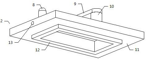
[0035] see figure 2 , the adhesive body 2 includes a pressing piece 9, a connecting column 10, an application seat 11, a frame 12 and a slot 13, the lower end of the pressing piece 9 is rotatably mounted on the upper end of the connecting column 10, and the lower end of the pressing piece 9 is squeezed on the suction cup 3 The upper end of the upper end of the connecting column 10 is fixedly connected to the upper end of the smearing seat 11, the upper end of the blocking frame 12 is fixedly connected with the lower end of the smearing seat 11, the draw-in groove 13 is opened symmetrically on the outer end of the smearing seat 11, and the rubber blocking frame 6 Fastened together with the card slot 13; use the pressure piece 9 to press the suction cup 3 on the upper side of the applicator seat 11 to prevent the suction cup 3 from falling off, thereby improving the stability of the assembly of the adhesive body 2 and the suction cup 3, which needs to be disassembled When the m...
Embodiment 3
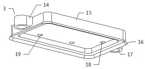
[0038] see image 3 , the suction cup 3 includes a connecting block 14, a sealing seat 15, a sealing ring 16, a vent hole 18 and a threading hole 19, the connecting block 14 is symmetrically arranged on the outside of the sealing seat 15, the connecting block 14 is fixedly connected with the sealing seat 15, and the sealing ring The upper end of 16 is fixedly connected to the lower end of the sealing seat 15, the lower end of the sealing ring 16 is adsorbed on the upper end of the smearing seat 11, the upper end of the sealing seat 15 is fixedly installed with the operating body 5, and the vent hole 18 is hollowed out at the lower end of the sealing seat 15 , the inner space of the ventilation hole 18 is connected with the inner space of the operation main body 5, and the threading hole 19 is hollowed out on the lower end side of the sealing seat 15; the threading hole 19 is sealed by the lead wire of the host 7; the connecting block 14 is slidably sleeved on the guide The out...
PUM
 Abstract
Description
Claims
Application Information
 - R&D
- Intellectual Property
- Life Sciences
- Materials
- Tech Scout
- Unparalleled Data Quality
- Higher Quality Content
- 60% Fewer Hallucinations
Browse by: Latest US Patents, China's latest patents, Technical Efficacy Thesaurus, Application Domain, Technology Topic, Popular Technical Reports.
© 2025 PatSnap. All rights reserved.Legal|Privacy policy|Modern Slavery Act Transparency Statement|Sitemap|About US| Contact US: help@patsnap.com


