Optical cable connector box and optical cable inlet clamping structure thereof

A technology of optical cable splice box and splice box, which is applied in the direction of fiber mechanical structure, optics, light guide, etc., can solve the problems of poor versatility of splice box, and achieve the effect of improving the scope of application

Pending Publication Date: 2021-10-22
STATE GRID ZHEJIANG ELECTRIC POWER
View PDF0 Cites 0 Cited by
  • Summary
  • Abstract
  • Description
  • Claims
  • Application Information

AI Technical Summary

Problems solved by technology

[0003] However, when the existing optical cable is connected to the optical cable splice box, each splice box can only be connected to an optical cable of one size, which makes the splice box poor in versatility

Method used


Image

  • Optical cable connector box and optical cable inlet clamping structure thereof

Examples


Embodiment Construction

[0023] The invention discloses an optical cable inlet clamping structure of an optical cable splice box to adapt to optical cables of different sizes. In addition, the invention also discloses an optical cable joint box with the above-mentioned optical cable inlet clamping structure.

[0024] The following will clearly and completely describe the technical solutions in the embodiments of the present invention with reference to the accompanying drawings in the embodiments of the present invention. Obviously, the described embodiments are only some, not all, embodiments of the present invention. Based on the embodiments of the present invention, all other embodiments obtained by persons of ordinary skill in the art without making creative efforts belong to the protection scope of the present invention.

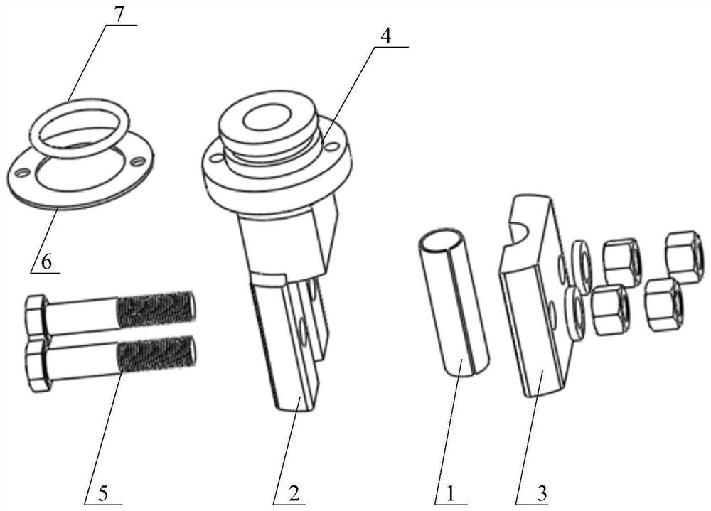
[0025] Such as figure 1 As shown, the present application discloses an optical cable inlet clamping structure of an optical cable splice box, including: an adapter 1 , a sealin...


PUM


Abstract

The invention discloses an optical cable inlet wire clamping structure of an optical cable connector box, which is characterized by comprising an adapter (1) used for sleeving the outer side of an optical cable with a wrapping skin; a sealing clamping piece which is used for clamping the optical cable and connecting the optical cable to a connector box in a sealing manner; the sealing clamping piece comprises a clamping piece arranged on the outer side of the adapter (1) in a sleeving mode and a sealing piece (4) fixedly connected with the clamping piece, the sealing piece (4) is arranged on the outer side of an optical fiber unit connected with the optical cable in a sleeving mode and connected with a connector box in a sealing mode, and the inner diameter of the clamping piece is adjustable; and an adjusting bolt (5) which is used for adjusting the inner diameter of the clamping piece through rotation. The optical cable is protected through the adapter, and the inner diameter of the clamping piece is changed through the clamping piece and the adjusting bolt which sleeve the outer side of the adapter, so that the optical cable connector box adapts to optical cables of different sizes, and the application range of the optical cable connector box is widened.

Description

technical field [0001] The invention relates to the technical field of electric equipment, in particular to an optical cable joint box and an optical cable inlet clamping structure thereof. Background technique [0002] Optical cable splice box, also known as optical cable splicing bag, optical cable splicing bag and gun barrel, belongs to the mechanical pressure sealing joint system. The optical cable splice box is an indispensable and important device in the field of communication. The optical cable splice box is a device for wiring and protecting optical cables. [0003] However, when an existing optical cable is connected to an optical cable splice box, each splice box can only be connected to an optical cable of one size, which makes the splice box poor in versatility. [0004] Therefore, how to provide an optical cable inlet clamping structure of an optical cable splice closure to adapt to optical cables of different sizes is an urgent problem to be solved by those sk...

Claims


Application Information

Patent Timeline
Patent Type & Authority Applications(China)
IPC IPC(8): G02B6/44
CPCG02B6/4446
Inventor 张明熙毛秀伟朱发强王嵚黄红兵范雪峰沈潇军刘晨阳范超贺家乐叶韵
Owner STATE GRID ZHEJIANG ELECTRIC POWER
Why Eureka
Try Eureka