Gas turbine applicable to whole territory

A gas turbine and boundary technology, applied in the direction of blade support components, machines/engines, stators, etc., can solve the problems of increasing engine starting design technology risks, increasing rotor-stator rubbing, poor aerodynamic performance, etc., to improve plateau starting performance , enhance the effect of plains

Active Publication Date: 2021-10-26
AECC HUNAN AVIATION POWERPLANT RES INST
View PDF5 Cites 0 Cited by
  • Summary
  • Abstract
  • Description
  • Claims
  • Application Information

AI Technical Summary

Problems solved by technology

[0004] At present, conventional gas turbine guide vanes adopt single or multi-joint design, and a single blade or 2 to 4 blades are installed on the connector through bolts to form a whole ring guide. The blades are cooled by air film, and the cooling air consumption is large. , A certain installation gap is reserved between the blade and the blade flow channel and sealed by the sealing sheet. The design of the connection and sealing mechanism is complicated, the number of parts is greatly increased, and the leading edge and mid-chord area of ​​the working blade are generally multi-cavity inside The backflow cooling structure, the blade body and the trailing edge adopt a small hole cooling structure, the aerodynamic performance is poor, it is easy to block in the sandy environment, and it is easy to accumulate salt particles in the saline environment, which will cause blade ablation, and the gas turbine is reliable. After the working blades are cooled, the pressure of the gas turbine disk cavity needs to be increased accordingly to realize the cooling of the working blades, and the static and rotational seal clearance of the disk cavity should be controlled within a small range (generally about 0.2mm ) to increase the pressure of the disk cavity and reduce the leakage of cold air from the disk cavity into the main gas channel through the rim of the disk cavity, which increases the risk of rubbing against the rotor and stator; when the gas turbine adopts the design of cooling blades, there will be a large proportion ( Up to about 20% of the cold air cannot effectively drive the gas turbine to do work, especially in the plateau environment where the air is thin and the engine is difficult to start, which further increases the technical risk of the engine start design
At the same time, due to the complex cooling structure of the blades, the manufacturing cost of the engine will increase significantly

Method used


Image

  • Gas turbine applicable to whole territory
  • Gas turbine applicable to whole territory
  • Gas turbine applicable to whole territory

Examples


Embodiment Construction

[0033] In order to make the purpose, technical solutions and advantages of the embodiments of the present invention more clear, the technical solutions in the embodiments of the present invention will be clearly and completely described below in conjunction with the accompanying drawings in the embodiments of the present invention. Obviously, the described embodiments It is a part of embodiments of the present invention, but not all embodiments. Based on the embodiments of the present invention, all other embodiments obtained by persons of ordinary skill in the art without making creative efforts belong to the protection scope of the present invention.

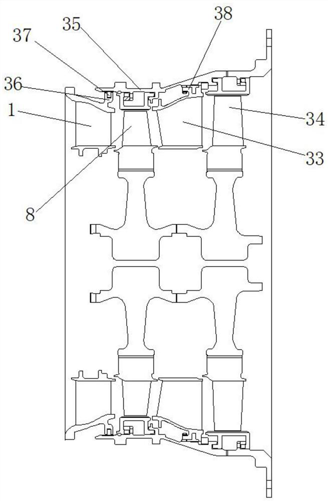
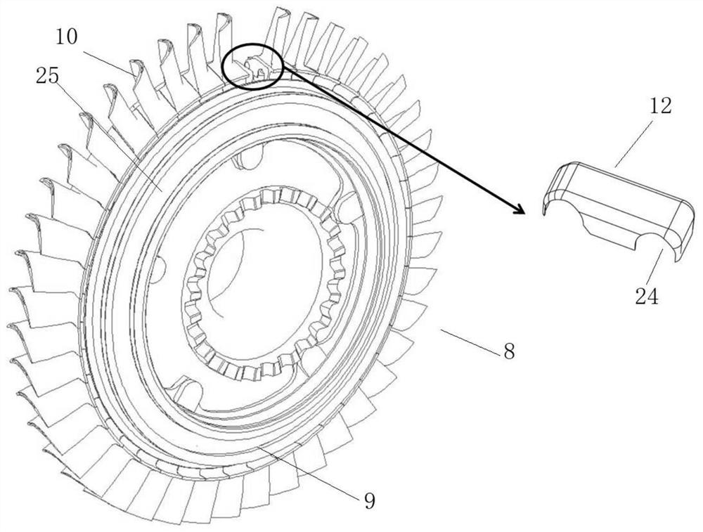
[0034] The present invention provides a gas turbine applicable to all territories, such as figure 1 As shown, the gas turbine includes a first-stage gas turbine and a second-stage gas turbine, and the first-stage gas turbine includes a first-stage guide 1 and a first-stage rotor 8 .

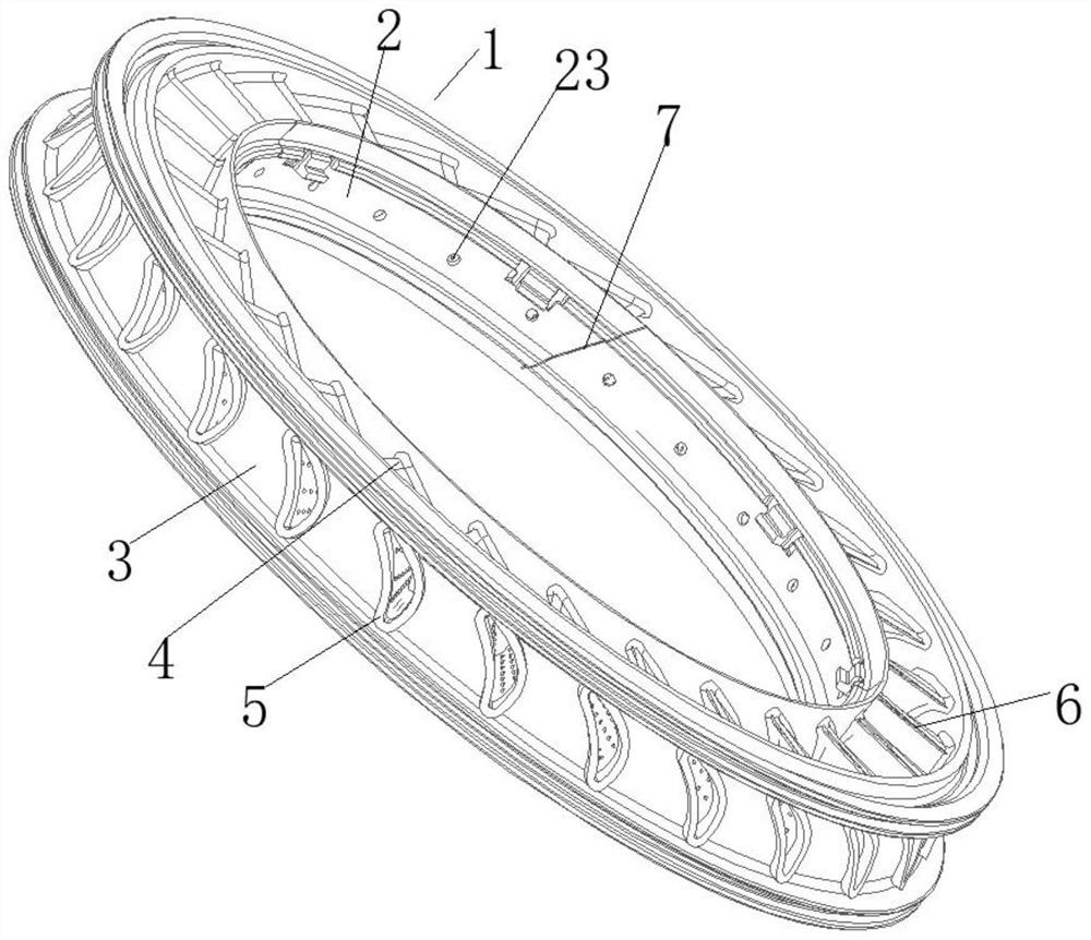
[0035] For the primary guide 1, the whole...


PUM


Abstract

The invention provides a gas turbine applicable to the whole territory. The gas turbine comprises a first-stage gas turbine, wherein the first-stage gas turbine comprises a first-stage guider, the first-stage guider comprises an inner ring, an outer ring and guide blades, the guide blades are arranged between the inner ring and the outer ring, an opening is formed in the outer wall of the outer ring, a deviation crack is formed in the tail edge of each guide blade, and an impact and turbulent flow structure is arranged in an inner cavity of each guide blade. According to the gas turbine, the cooling of the guide blades is effectively realized.

Description

technical field [0001] The invention belongs to the technical field of gas turbines, in particular to a gas turbine applicable to all areas. Background technique [0002] Gas turbine is one of the core components of aviation gas turbine shaft engine. It is a turbomachinery that converts the energy of high-temperature and high-pressure gas into kinetic energy and mechanical energy. The gas turbine consists of a guide, a rotor and an outer ring of the gas turbine. The high-temperature and high-pressure gas flows from the inlet of the gas turbine through the guide blades to turn and expand, converting the potential energy of the gas into kinetic energy of the gas. The high-speed gas drives the working blades to rotate through the gas turbine rotor to generate mechanical work, and is transmitted to the compressor by the gas turbine shaft for air compression. The quality of gas turbine design determines the overall design level of aero-engines, and its development level plays a ...

Claims


Application Information

Patent Timeline
Patent Type & Authority Applications(China)
IPC IPC(8): F01D9/02F01D9/04F01D25/12F01D5/16F01D5/14F01D5/28
CPCF01D9/02F01D9/041F01D25/12F01D5/16F01D5/147F01D5/141F01D5/288
Inventor 包幼林甘明瑜廖乃冰曾飞余索远
Owner AECC HUNAN AVIATION POWERPLANT RES INST
Why Eureka
Try Eureka