
Railway turnout external locking device

An external locking and locking technology, which is applied to the locking mechanism of turnouts, railway signals, railway car body parts, etc., can solve the problems of lack of sealing performance, inability to lock the position of the tip rail, and rust.

Pending Publication Date: 2021-10-29
CRSC RESEARCH & DESIGN INSTITUTE GROUP CO LTD
View PDF0 Cites 0 Cited by
  • Summary
  • Abstract
  • Description
  • Claims
  • Application Information

AI Technical Summary

Problems solved by technology

[0005] However, the existing external locking devices for turnouts can only lock the close-fitting position of the switch rail, but cannot lock the repelling position of the switch rail, resulting in poor stability of the switch rail repelling from the basic rail. The point rails separated from the basic rails are prone to vibration due to impact loads, which will lead to serious deformation and shorten the service life of the turnouts
[0006] In addition, with the continuous development of my country's railways, the environment of the external locking device of the turnout is getting worse and worse. The external locking device in practical application will be worn or rusted due to factors such as sand, ice and snow immersion, which will lead to the jamming phenomenon of the turnout
The existing external locking devices of turnouts do not have good sealing performance, resulting in low reliability and increased follow-up maintenance workload and maintenance costs

Method used


Image

  • Railway turnout external locking device
  • Railway turnout external locking device
  • Railway turnout external locking device

Examples


Embodiment Construction

[0056] The present invention will be further described in detail below in conjunction with the accompanying drawings and embodiments. It should be understood that the specific embodiments described here are only used to explain the present invention, but not to limit the present invention. In addition, it should be noted that, for the convenience of description, only some structures related to the present invention are shown in the drawings but not all structures.

[0057] In the description of the present invention, unless otherwise clearly specified and limited, the terms "connected", "connected" and "fixed" should be understood in a broad sense, for example, it can be a fixed connection, a detachable connection, or an integrated ; It can be a mechanical connection or an electrical connection; it can be a direct connection or an indirect connection through an intermediary, and it can be the internal communication of two components or the interaction relationship between two ...


PUM


Abstract

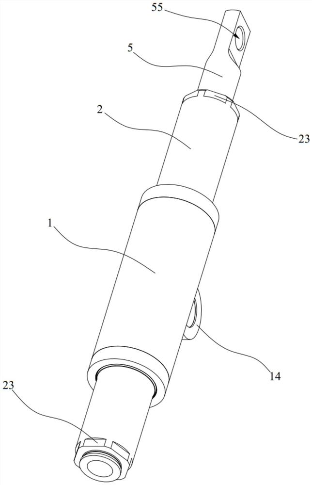
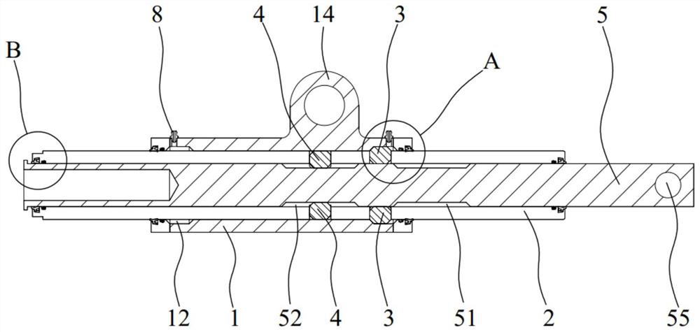
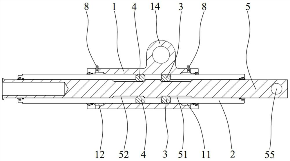
The invention belongs to the technical field of railway traffic, and discloses a railway turnout external locking device which comprises a locking cylinder, a locking sleeve, a first locking block, a second locking block and a locking rod, the locking cylinder is connected to a stock rail, the locking sleeve is connected to a switch rail, the locking sleeve is movably installed in the locking cylinder in a penetrating mode, and the locking rod is installed in the locking sleeve in a penetrating mode. The locking sleeve has a first limit position and a second limit position when driving the switch rail to move, namely a close attaching position and a repulsion position corresponding to the switch rail. The locking rod can drive the locking sleeve to move between two limit positions through the first locking block or the second locking block, when the locking sleeve moves to the first limit position, the first locking block can be clamped in the first limiting groove, and when the locking sleeve moves to the second limit position, the first locking block can be clamped in the second limiting groove. The locking sleeve can be locked and fixed at the two extreme positions, namely, the switch rail connected with the locking sleeve can be locked and fixed at the close attaching position and the repulsion position, the stability when a vehicle passes through the turnout is guaranteed, and potential safety hazards are reduced.

Description

technical field [0001] The invention relates to the technical field of railway traffic, in particular to an external locking device for a railway turnout. Background technique [0002] A turnout is a line connection device that allows a train to transfer from one track to another. It is also one of the weak links of the track and is usually laid in large numbers at stations and marshalling yards. By setting the turnout, the passing capacity of the line can be brought into full play. Even if it is a single-track railway, by laying the turnout and building a section of forked line larger than the length of the train, the train can be separated. [0003] A common common single-opening turnout includes two basic rails arranged at intervals and two switch rails arranged at intervals. The two switch rails are located between the two basic rails. The basic rail of the first rail is closely attached, and the other tip rail is separated from the basic rail close to it. After the sto...

Claims


Application Information

Patent Timeline
Patent Type & Authority Applications(China)
IPC IPC(8): B61L5/10
CPCB61L5/10
Inventor 孙晓勇谢博才黄天新张玉林陈昊张凉刘尚超刘振华李宇飞杨硕李继薛家兵
Owner CRSC RESEARCH & DESIGN INSTITUTE GROUP CO LTD
Learn More