Supercharge Your Innovation With Domain-Expert AI Agents!

Rotating chromatic range sensor system with calibration objects and method

一种对象、色度的技术,应用在色度范围传感器光学探针领域,能够解决执行、校准难以准确地执行、难测量地点等问题

Active Publication Date: 2021-10-29
MITUTOYO CORP
View PDF14 Cites 0 Cited by
  • Summary
  • Abstract
  • Description
  • Claims
  • Application Information

AI Technical Summary

Problems solved by technology

However, especially for rotating probes, calibration using an interferometer is difficult to perform accurately
Additionally, such calibrations can be difficult to perform at measurement locations such as manufacturing facilities

Method used


Image

  • Rotating chromatic range sensor system with calibration objects and method
  • Rotating chromatic range sensor system with calibration objects and method
  • Rotating chromatic range sensor system with calibration objects and method

Examples


Embodiment Construction

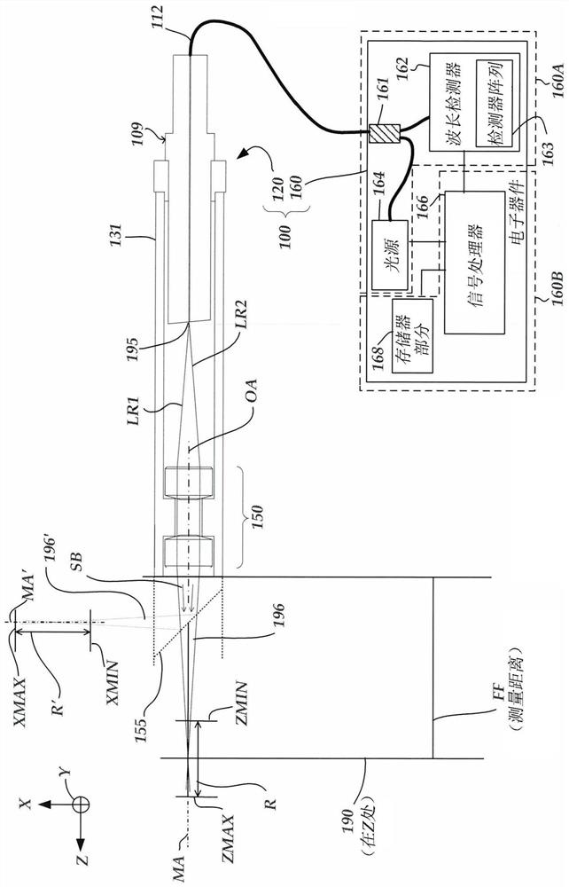
[0046] figure 1 is a block diagram of an exemplary colorimetric sensor (CRS) system 100 of a first type based on the principles of operation expected to be used in conjunction with a coordinate measuring machine. The CRS system 100 has certain similarities to the systems described in US Patent Nos. 7,876,456 and 7,990,522 (the '456 and '522 patents, respectively), which are hereby incorporated by reference in their entirety. As shown in FIG. 1 , CRS system 100 includes optics 120 and electronics 160 . It should be understood that figure 1 The illustrated CRS system 100 is a color point sensor system that, in some cases, can measure a single measurement point at a time. figure 1 The illustrated optical element 120 is an optical pen. However, in various embodiments, alternative types of chromaticity range systems may be utilized, such as chromaticity line sensors.

[0047] Optical pen 120 includes fiber optic connector 109 , housing 131 (eg, assembly tube) and optics portion...


PUM


Abstract

A calibration configuration for a chromatic range sensor (CRS) optical probe of a coordinate measurement machine (CMM) includes a cylindrical calibration object and a spherical calibration object. The cylindrical calibration object includes at least a first nominally cylindrical calibration surface having a central axis that extends along a Z direction that is intended to be aligned approximately parallel to a rotation axis of the CRS optical probe. The spherical calibration object includes a nominally spherical calibration surface having a first plurality of surface portions. The CMM is operated to obtain radial distance measurements and determine cylindrical calibration data using radial distance measurements of the cylindrical calibration object and to determine spherical calibration data using radial distance measurements of the spherical calibration object.

Description

technical field [0001] The present disclosure relates generally to precision measuring instruments, and more particularly to optical probes such as colorimetric range sensors that may be used with a coordinate measuring machine (CMM) to determine measurements of a workpiece. Background technique [0002] In one type of coordinate measuring machine, a stylus is used to scan the surface of a workpiece. After scanning, a three-dimensional profile of the workpiece is provided. In one type of scanning probe, the workpiece is measured directly by bringing the probe's mechanical contacts into contact with various points along the surface of the workpiece. In some cases, the mechanical contacts are balls. [0003] In other coordinate measuring machines, an optical probe is used that measures the workpiece without physical contact with the surface. Some optical probes (e.g., triangulation probes) utilize light to measure workpiece surface points, and some optical probes include ca...

Claims


Application Information

Patent Timeline
Patent Type & Authority Applications(China)
IPC IPC(8): G01B11/00
CPCG01B11/005G01B11/0608G01B2210/50G01B21/042G01B11/24G01B9/0205G01B7/012
Inventor J.D.托比亚森
Owner MITUTOYO CORP
Features
  • R&D
  • Intellectual Property
  • Life Sciences
  • Materials
  • Tech Scout
  • Unparalleled Data Quality
  • Higher Quality Content
  • 60% Fewer Hallucinations
Learn More