Intelligent detection device for online broken wire and strand separation of hoisting wire rope
An intelligent detection and wire rope technology, applied in the field of wire rope detection, can solve problems such as difficult to achieve detection effect, and achieve good detection effect and accurate results
- Summary
- Abstract
- Description
- Claims
- Application Information
AI Technical Summary
Problems solved by technology
Method used
Image
Examples
Embodiment 1
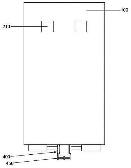
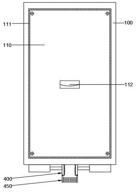
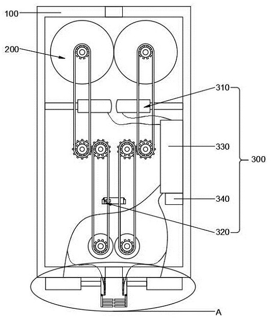
[0042] see again Figure 1-Figure 8 , the present invention provides a technical solution: an intelligent detection device for online broken wires and strands of hoisting wire ropes, including:
[0043] The device housing 100 has rope slots on the same axis at both ends;
[0044] The driving assembly 200 is installed inside the device housing 100, and the two groups of driving parts are respectively located on both sides of the device housing 100;
[0045] The broken wire and strand detection assembly 300 includes a diameter detection assembly 310, a burr detection assembly 320, a central control module 330 and an alarm 340. The diameter detection assembly 310 is installed on the inner side of the device housing 100, and the burr The detection assembly 320 is installed on the other side of the device housing 100, the central control module 330 and the alarm 340 are connected to the inner side of the device housing 100 by bolts, the diameter detection assembly 310 and the burr...
Embodiment 2
[0048] see again Figure 1-Figure 8 The difference between this embodiment and Embodiment 1 is that the drive assembly 200 includes a drive motor 210, a first belt gear 220, a first transmission belt 230, a second belt gear 240, a first transmission gear 250, and a second transmission gear 260 , the third belt gear 270, the second transmission belt 280 and the fourth belt gear 290, the fixed parts of the two drive motors 210 are all connected to the outer front wall of the device housing 100 by bolts, the two drive motors 210 The rotating parts of the rotating parts all pass through the device housing 100 and are connected to the first belt gear 220 by bolts, the first belt gear 220 is connected to the second belt gear 240 through the first transmission belt 230, and the first transmission belt is welded below the second belt gear 240. Gear 250, one side of the first transmission gear 250 meshes with the second transmission gear 260, the top of the second transmission gear 260...
Embodiment 3
[0051] see again Figure 1-Figure 8 The difference between this embodiment and Embodiment 1 is that the diameter detection assembly 310 includes a sensing rod 311, a contact rod 312, a movable groove 313, a pressure sensor 314 and a push spring 315, and the two sensing rods 311 are passed through bolts respectively. Connected to the inner side walls of the device housing 100, one end of the sensing rod 311 is connected to the contact rod 312 through the movable groove 313, and the movable groove 313 is opened inside the contact rod 312, and one end of the movable groove 313 is connected by a bolt A pressure sensor 314, the other end of the movable groove 313 is welded to one end of a push spring 315, and the other end of the push spring 315 is welded to the induction rod 311;
[0052] The sensing rod 311 is used to connect the device housing 100 and the contact rod 312, the contact rod 312 is used to contact and fit the steel wire rope, the movable groove 313 is used to provid...
PUM
 Abstract
Description
Claims
Application Information
 - R&D
- Intellectual Property
- Life Sciences
- Materials
- Tech Scout
- Unparalleled Data Quality
- Higher Quality Content
- 60% Fewer Hallucinations
Browse by: Latest US Patents, China's latest patents, Technical Efficacy Thesaurus, Application Domain, Technology Topic, Popular Technical Reports.
© 2025 PatSnap. All rights reserved.Legal|Privacy policy|Modern Slavery Act Transparency Statement|Sitemap|About US| Contact US: help@patsnap.com


