
Reverse positioning clamping mechanism

A technology for positioning and clamping mechanisms and fixing parts, applied in workpiece clamping devices, manufacturing tools, etc., can solve problems such as difference in alignment results, time-consuming and labor-intensive, and achieve the effect of ensuring parallelism

Pending Publication Date: 2021-11-02
软控联合科技有限公司
View PDF0 Cites 0 Cited by
  • Summary
  • Abstract
  • Description
  • Claims
  • Application Information

AI Technical Summary

Problems solved by technology

[0003] The main purpose of the present invention is to provide an anti-positioning clamping mechanism to solve the problems in the prior art that it takes time and effort to align mold parts, and there are differences in alignment results

Method used


Image

  • Reverse positioning clamping mechanism
  • Reverse positioning clamping mechanism

Examples


Embodiment Construction

[0021] It should be noted that, in the case of no conflict, the embodiments in the present application and the features in the embodiments can be combined with each other. The present invention will be described in detail below with reference to the accompanying drawings and examples.

[0022] It should be noted that, unless otherwise specified, all technical and scientific terms used in this application have the same meaning as commonly understood by those of ordinary skill in the art to which this application belongs.

[0023] In the present invention, unless stated otherwise, the used orientation words such as "upper, lower, top, bottom" are usually for the directions shown in the drawings, or for the parts themselves in the vertical, In terms of vertical or gravitational direction; similarly, for the convenience of understanding and description, "inner and outer" refer to the inner and outer relative to the outline of each component itself, but the above orientation words ...


PUM


Abstract

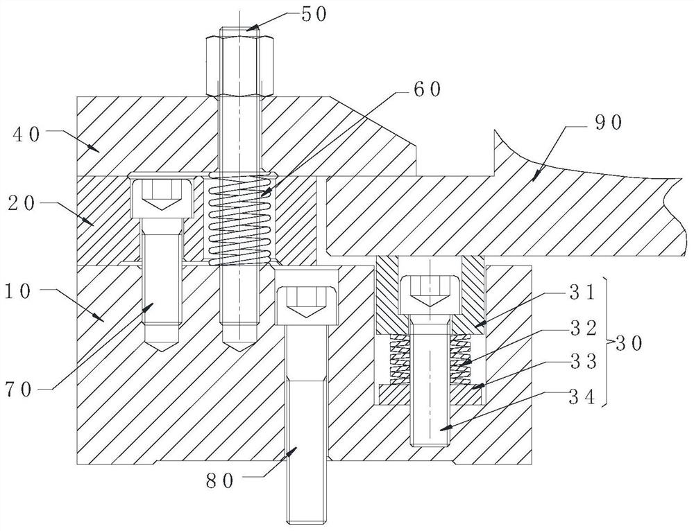
The invention provides a reverse positioning clamping mechanism. The reverse positioning clamping mechanism comprises a base, a positioning equal-height block, a jacking assembly and a pressing plate, wherein the positioning equal-height block is arranged on the base; the jacking assembly is movably connected with the base, the height of the portion, protruding out of the upper surface of the base, of the jacking assembly is adjustable, and the lower surface of a workpiece abuts against and is supported on the upper surface of the jacking assembly; and the pressing plate is movably arranged above the positioning equal-height block, the lower surface of the pressing plate is in contact with and extrudes the upper surface of the positioning equal-height block and the upper surface of the workpiece at the same time, and the upper surface of the positioning equal-height block is flush with the upper surface of the workpiece. According to the reverse positioning clamping mechanism, the problems that in the prior art, time and labor are wasted for alignment of mold parts, and alignment results are different are solved.

Description

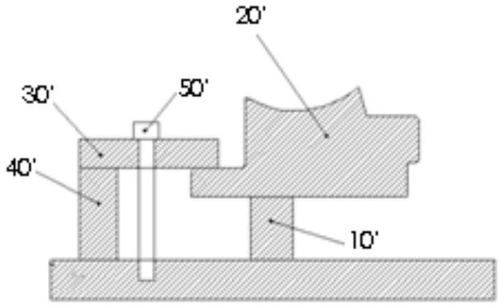
technical field [0001] The invention relates to the technical field of tire processing, in particular to a reverse positioning clamping mechanism. Background technique [0002] During the existing tire mold processing, such as figure 1 As shown, the processing and positioning of the side plate parts in the mold parts uses four standard contour blocks 10' to align the workpiece 20', place the workpiece 20' on the contour block 10', and then use the dial gauge to Alignment of the workpiece includes alignment of flatness and roundness, and then pressing the workpiece with the pressing plate 30', the support block 40' and the bolt 50'. Alignment takes a lot of time, the work efficiency of the operator is low, and there are differences in the alignment results of each workpiece, resulting in inconsistent size and depth of the movable type block grooves when processing the side plates, which will cause hidden dangers to subsequent processing. Serious size defects will lead to sid...

Claims


Application Information

Patent Timeline
Patent Type & Authority Applications(China)
IPC IPC(8): B25B11/00
CPCB25B11/00
Inventor 张洪斌周传海王亚东
Owner 软控联合科技有限公司
Learn More