Telecentric lens

A telecentric lens and superlens technology, applied in the optical field, can solve the problems of large size of telecentric lens, complex manufacturing process and high manufacturing cost, and achieve the effects of small size, low mass production cost and high consistency

Pending Publication Date: 2021-12-21
SHENZHEN METALENX TECH CO LTD
View PDF6 Cites 2 Cited by
  • Summary
  • Abstract
  • Description
  • Claims
  • Application Information

AI Technical Summary

Problems solved by technology

[0005] In order to solve the technical problems of large size, complex structure, complex manufacturing process and high manufacturing cost of the telecentric lens in the related art, the embodiment of the present application provides a telecentric lens, and the technical solution is as follows

Method used


Image

  • Telecentric lens
  • Telecentric lens
  • Telecentric lens

Examples


Embodiment 1

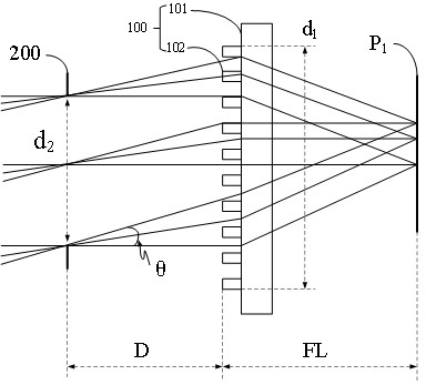
[0143] The embodiment of the present application provides a kind of figure 2 The specific parameters of the telecentric lens shown are shown in Table 1A, and the implementation effect of the telecentric lens is shown in Table 1B. The point spread functions of the three fields of view (0 field of view, 0.5 field of view and 1.0 field of view) of the telecentric lens are as follows Figure 8 to Figure 10 As shown, the corresponding modulation transfer function is as Figure 11 shown.

[0144]

[0145] As shown in Table 1B, the chief ray angle of the telecentric lens provided in Example 1 is less than or equal to 0.6°. Figure 8 to Figure 10 shows the point spread function of the light modulated by the telecentric lens, as Figure 8 to Figure 10 As shown, the point spread function ambiguity of the telecentric lens provided by Embodiment 1 is low, and the imaging is clear. Figure 11 It shows that the modulation transfer functions of the telecentric lens provided by Embodi...

Embodiment 2

[0147] The embodiment of the present application provides a kind of figure 2 The specific parameters of the telecentric lens shown are shown in Table 2A, and the implementation effect of the telecentric lens is shown in Table 2B. The point spread functions of the three fields of view (0 field of view, 0.5 field of view and 1.0 field of view) of the telecentric lens are as follows Figure 12 to Figure 14 As shown, the corresponding modulation transfer function is as Figure 15 shown.

[0148]

[0149] As shown in Table 2B, the chief ray angle of the telecentric lens provided in Example 2 is less than or equal to 1°. Figure 12 to Figure 14 shows the point spread function of the light modulated by the telecentric lens, as Figure 12 to Figure 14As shown, the telecentric lens provided by Embodiment 2 has a low point spread function ambiguity and a clear image. Figure 15 It shows that the modulation transfer functions of the telecentric lens provided by Embodiment 2 all r...

Embodiment 3

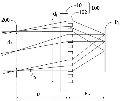
[0151] The embodiment of the present application provides a kind of figure 1 The specific parameters of the telecentric lens shown are shown in Table 3A, and the implementation effect of the telecentric lens is shown in Table 3B. The point spread functions of the three fields of view (0 field of view, 0.5 field of view and 1.0 field of view) of the telecentric lens are as follows Figure 16 to Figure 18 As shown, the corresponding modulation transfer function is as Figure 19 shown.

[0152]

[0153] As shown in Table 3B, the chief ray angle of the telecentric lens provided in Example 3 is less than or equal to 3°. Figure 16 to Figure 18 shows the point spread function of the light modulated by the telecentric lens, as Figure 16 to Figure 18 As shown, the telecentric lens provided by Example 3 has a low point spread function ambiguity and a clear image. Figure 19 It shows that the modulation transfer functions of the telecentric lens provided by Embodiment 3 under di...


PUM


Abstract

The invention provides a telecentric lens and a laser radar system comprising the telecentric lens, and belongs to the technical field of optics. The telecentric lens comprises a first super lens and a diaphragm, wherein the first super lens comprises a first plane substrate and first nano structures; the first nano structures are arranged on one side of the first plane substrate, and the first nano structures are arranged periodically; and the diaphragm and the first super lens are matched with the same optical axis so that the chief ray angle of incident light in the object space or the image space of the first super lens is smaller than 8 degrees. The telecentric lens provided by the embodiment of the invention is simple in structure, small in size, low in mass production cost and high in consistency, and the chief ray angle is smaller than 8 degrees.

Description

technical field [0001] The present application relates to the field of optical technology, in particular to a telecentric lens. Background technique [0002] A telecentric lens is a lens in which the chief ray (that is, the ray passing through the center of the aperture stop) is parallel in object space and / or image space. The telecentric lens has the advantages of constant magnification performance and constant imaging perspective, which can overcome the optical distortion of imaging. [0003] A telecentric lens in the related art requires many lenses, and usually high dispersion glass is used to manufacture one or more negative focus lenses. [0004] The number of lenses in the telecentric lens in the related art is large, especially multiple negative focus lenses are required, which leads to the problems of large size, complex structure, complicated manufacturing process and high manufacturing cost of the telecentric lens. Contents of the invention [0005] In order t...

Claims


Application Information

Patent Timeline
Patent Type & Authority Applications(China)
IPC IPC(8): G02B13/22G02B3/00G01S7/481
CPCG02B13/22G02B3/0037G01S7/4811
Inventor 郝成龙谭凤泽朱健
Owner SHENZHEN METALENX TECH CO LTD
Why Eureka
Try Eureka