
A kind of rapid prototyping equipment for lightweight glass container and using method thereof

A technology for glass containers and molding equipment, which is applied in glass molding, glass manufacturing equipment, transmission machinery dedicated to glass blowing machines, etc., and can solve the problems of intermittent feeding, inaccuracy, and inability to automatically switch molds and clamping stations.

Active Publication Date: 2022-04-15
SHANDONG JINGYAO GLASS GRP
View PDF6 Cites 0 Cited by
  • Summary
  • Abstract
  • Description
  • Claims
  • Application Information

AI Technical Summary

Problems solved by technology

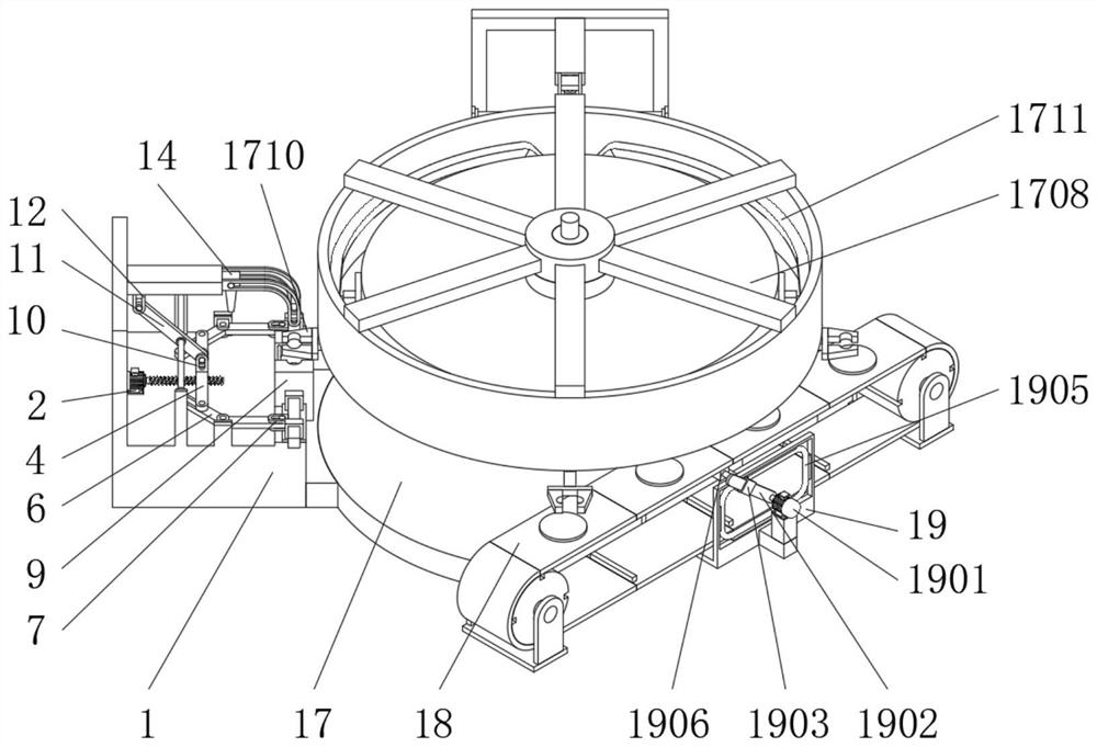
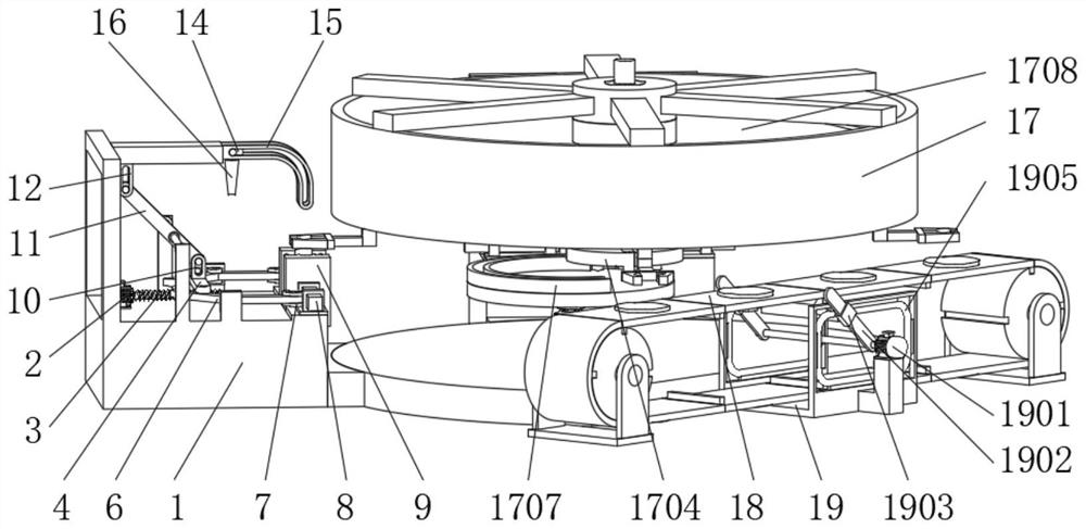
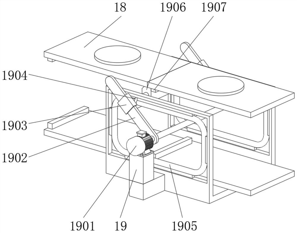
[0004] The purpose of the present invention is to solve the problems in the prior art that the materials cannot be fed intermittently, the stations cannot be switched automatically, and the mold clamping is not accurate, and a light-weight glass container rapid prototyping equipment and its application method are proposed.

Method used


Image

  • A kind of rapid prototyping equipment for lightweight glass container and using method thereof
  • A kind of rapid prototyping equipment for lightweight glass container and using method thereof
  • A kind of rapid prototyping equipment for lightweight glass container and using method thereof

Examples


Embodiment Construction

[0036] The following will clearly and completely describe the technical solutions in the embodiments of the present invention with reference to the accompanying drawings in the embodiments of the present invention. Obviously, the described embodiments are only some, not all, embodiments of the present invention.

[0037] In describing the present invention, it should be understood that the terms "upper", "lower", "front", "rear", "left", "right", "top", "bottom", "inner", " The orientation or positional relationship indicated by "outside", etc. is based on the orientation or positional relationship shown in the drawings, and is only for the convenience of describing the present invention and simplifying the description, rather than indicating or implying that the referred device or element must have a specific orientation, so as to Specific orientation configurations and operations, therefore, are not to be construed as limitations on the invention.

[0038] refer to Figure ...


PUM


Abstract

The invention discloses a lightweight glass container rapid prototyping device and a method for using the same, which belong to the technical field of glass container forming. A lightweight glass container rapid prototyping device comprises a forming frame, a telescopic connecting plate, a rotating bent plate, and a sliding orifice plate , a mold push rod, a rotating connecting plate, a supporting connecting rod, a limit slide rail and a forming frame, the top of the forming frame is fixedly connected with a forming motor, and the output end of the forming motor is installed to drive the telescopic connecting plate horizontally Sliding threaded rods, both ends of the telescopic connecting plate are movably connected with rotating hole slots for driving the rotating bending plate to rotate horizontally, the lightweight glass container rapid prototyping equipment and its use method, by setting the rotating bending plate, The movement of the telescopic connecting plate drives the two sets of rotating bending plates to rotate relative to each other through the two sets of rotating holes, so that the rotation of the rotating bending plate drives the two sets of forming molds connected with the mold push rod to move relatively through the sliding orifice plate to realize the mold clamping of the forming molds operate.

Description

technical field [0001] The invention relates to the technical field of glass container forming, in particular to a lightweight glass container rapid forming equipment and a use method thereof. Background technique [0002] Glass containers are made of more than a dozen raw materials such as cullet, soda ash, sodium nitrate, shellfish, and quartz sand. They are made by melting and shaping at a temperature of 1600 degrees. They can be produced according to different molds. Shaped glass bottles, mainly include various wine bottles, beverage bottles, pickle bottles, honey bottles, canned bottles, soda bottles, carbonated beverage bottles, coffee bottles, tea cups and other special-shaped glass bottles. To store products that are highly sensitive to humidity, the glass bottle container is a transparent container made by blowing and molding molten glass material. [0003] However, the current rapid prototyping equipment for glass containers has the problem of being unable to inte...

Claims


Application Information

Patent Timeline
Patent Type & Authority Patents(China)
IPC IPC(8): C03B7/02C03B9/40C03B9/44
CPCC03B7/02C03B9/40C03B9/44
Inventor 唐永
Owner SHANDONG JINGYAO GLASS GRP
Learn More