
Optical device

An optical device and guide post technology, applied in optics, optical components, instruments, etc., to improve light collection efficiency, prevent phase truncation, and reduce image distortion

Active Publication Date: 2021-11-05
VISERA TECH CO LTD
View PDF10 Cites 0 Cited by
  • Summary
  • Abstract
  • Description
  • Claims
  • Application Information

AI Technical Summary

Problems solved by technology

[0004] However, existing metalenses are not satisfactory in every respect

Method used


Image

  • Optical device
  • Optical device
  • Optical device

Examples


Embodiment Construction

[0041] The following disclosure provides many different embodiments or examples for implementing different features of the present invention. The following disclosure describes specific examples of various components and their arrangements to simplify the description. Of course, these specific examples are not intended to be limiting. For example, if an embodiment of the present disclosure describes that a first characteristic component is formed on or above a second characteristic component, it may include embodiments in which the first characteristic component is in direct contact with the second characteristic component, and also Embodiments may be included in which additional features are formed between the first and second features such that the first and second features may not be in direct contact.

[0042] It should be understood that additional operational steps may be performed before, during or after the method, and in other embodiments of the method, some of the o...


PUM

PropertyMeasurementUnit
diameteraaaaaaaaaa
refractive indexaaaaaaaaaa

Abstract

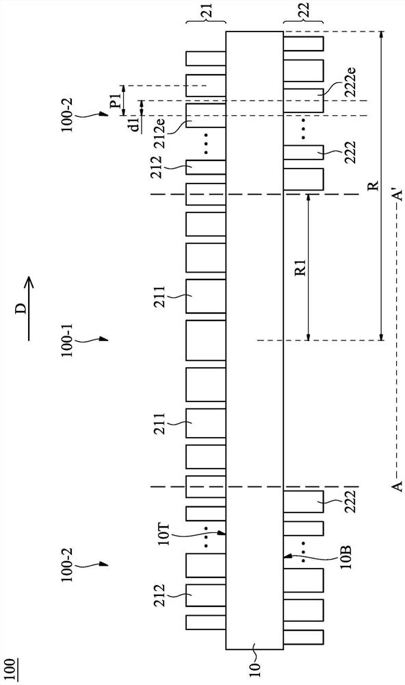
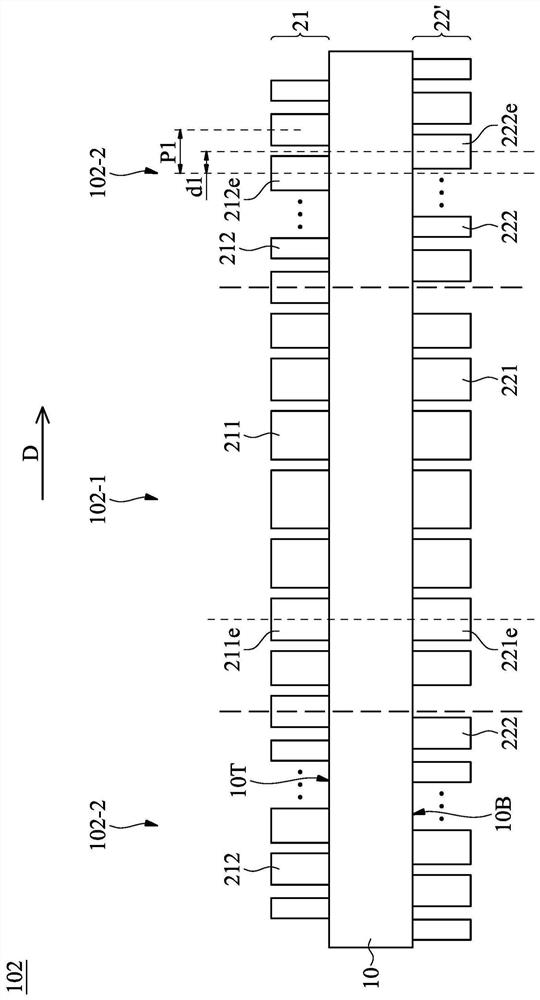
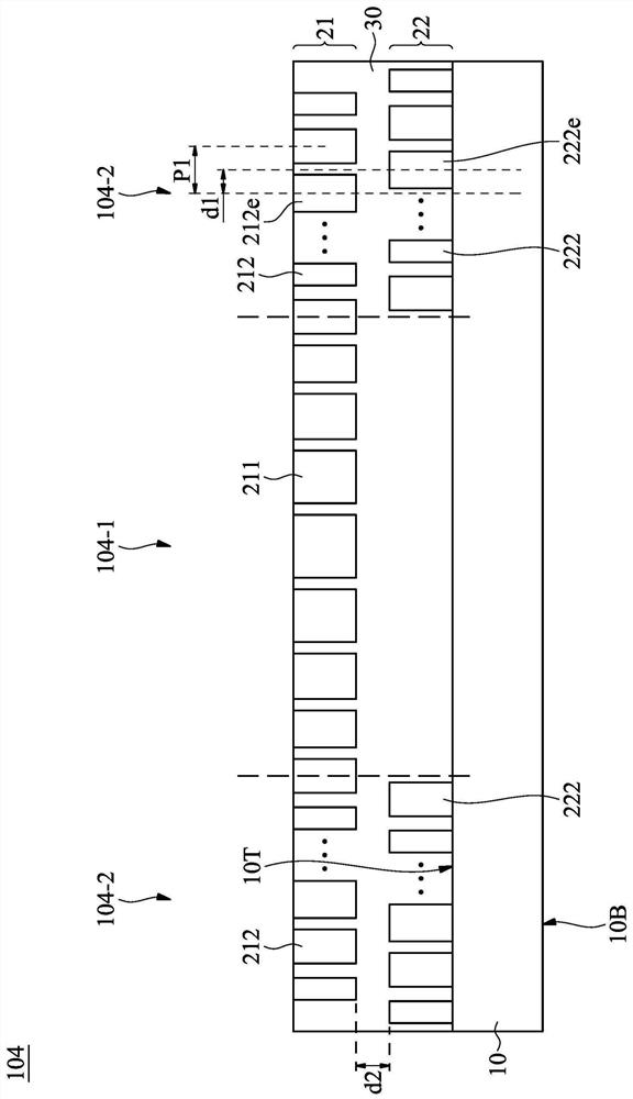
An optical device having a first region and a second region surrounding the first region is provided. The optical device includes a substrate. The optical device also includes a first meta-structure disposed on the substrate and having a plurality of first peripheral pillars in the second region. The optical device further includes a second meta-structure disposed on the substrate and having a plurality of second peripheral pillars corresponding to the plurality of first peripheral pillars. Each of the second peripheral pillars has a first shifting distance with respect to a corresponding first peripheral pillar in the radiation direction from the center of the optical device to the edge of the optical device.

Description

technical field [0001] Embodiments of the present disclosure relate to an optical device, in particular to an optical device comprising at least two meta-structures. Background technique [0002] In general, conventional optical lenses such as color filters, condenser lenses, and beamsplitters must be combined to provide a specific function. In addition, to eliminate the chromatic effect (which degrades its performance in panchromatic imaging applications), designers must integrate multiple lenses with opposite dispersion. These traditional optical lenses can make the end equipment in which they are used bulky. [0003] In recent years, thin lenses with focusing effects, called meta-lenses, have been developed. A metalens has a nanostructure that uses high refractive index materials to change the optical phase. Compared with traditional optical lenses, this structure greatly improves the volume and weight. [0004] However, existing metalenses are not satisfactory in eve...

Claims


Application Information

Patent Timeline
Patent Type & Authority Applications(China)
IPC IPC(8): G02B3/00G02B1/02G02B1/14
CPCG02B3/00G02B1/02G02B1/002G02B1/14G02B2003/0093G02B3/0006G02B3/08
Inventor 林国峰谢锦全
Owner VISERA TECH CO LTD
Learn More