Thermal insulation cotton sliver feeding manipulator capable of being placed in front and back and left and right staggering mode at intervals
A technology of manipulator and cotton sliver, which is applied in the direction of thin material handling, transportation and packaging, object supply, etc. It can solve the problems of slow feeding speed, low production efficiency, and long working time, so as to improve production efficiency, reduce energy consumption, The effect of shortening the working time
- Summary
- Abstract
- Description
- Claims
- Application Information
AI Technical Summary
Problems solved by technology
Method used
Image

Examples
Embodiment Construction
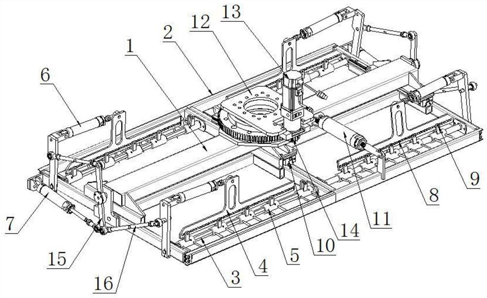
[0018] Such as figure 1 As shown, a thermal insulation sliver feeding manipulator that can be misplaced front and back and placed at intervals from left to right includes a hanger 1, and a fixture is installed on the lower part of the hanger 1. The fixture is installed on the hanger 2 by a hanger 2 and two front and back The support shaft 3 on the top, the jaws set on the support shaft 3, the swing arm 15 installed on the hanger 2, the connecting rod 16 installed on the swing arm 16, the connecting rod installed between the hanger 2 and the swing arm The clamping drive cylinder 7 and the horizontal drive cylinder 6 connected between the connecting rod and the jaws are composed; the clamps are two and arranged left and right, one of the clamps is fixedly installed with the hanger 1, and the other clamp is connected to the hanger 1 through the slideway 10 The hanger 1 is slidably installed back and forth, and a longitudinal drive cylinder 11 is connected between the hanger 1 and...
PUM
 Abstract
Description
Claims
Application Information
 - Generate Ideas
- Intellectual Property
- Life Sciences
- Materials
- Tech Scout
- Unparalleled Data Quality
- Higher Quality Content
- 60% Fewer Hallucinations
Browse by: Latest US Patents, China's latest patents, Technical Efficacy Thesaurus, Application Domain, Technology Topic, Popular Technical Reports.
© 2025 PatSnap. All rights reserved.Legal|Privacy policy|Modern Slavery Act Transparency Statement|Sitemap|About US| Contact US: help@patsnap.com