Feeding mechanism of fluid coating device and fluid coating device with same

A coating device and fluid technology, which is applied to the device and coating of the surface coating liquid, can solve the problems of inconvenient assembly and operation, inability to realize automatic operation, complex structure, etc., and achieve simple structure and high feeding speed Fast and stable results

Pending Publication Date: 2018-09-04
CHANGZHOU MINGSEAL ROBOT TECH CO LTD
View PDF0 Cites 0 Cited by
  • Summary
  • Abstract
  • Description
  • Claims
  • Application Information

AI Technical Summary

Problems solved by technology

One person can operate up to 2 machines, and cannot realize automatic operation
In addition, the structure of the

Method used


Image

  • Feeding mechanism of fluid coating device and fluid coating device with same

Examples


Embodiment Construction

[0027] Embodiments of the present invention are described in detail below, examples of which are shown in the drawings, wherein the same or similar reference numerals designate the same or similar elements or elements having the same or similar functions throughout. The embodiments described below by referring to the figures are exemplary only for explaining the present invention and should not be construed as limiting the present invention.

[0028] In describing the present invention, it is to be understood that the terms "center", "longitudinal", "transverse", "length", "width", "thickness", "upper", "lower", "front", " Back", "Left", "Right", "Vertical", "Horizontal", "Top", "Bottom", "Inner", "Outer", "Clockwise", "Counterclockwise", "Axial", The orientation or positional relationship indicated by "radial", "circumferential", etc. is based on the orientation or positional relationship shown in the drawings, and is only for the convenience of describing the present inventi...


PUM


Abstract

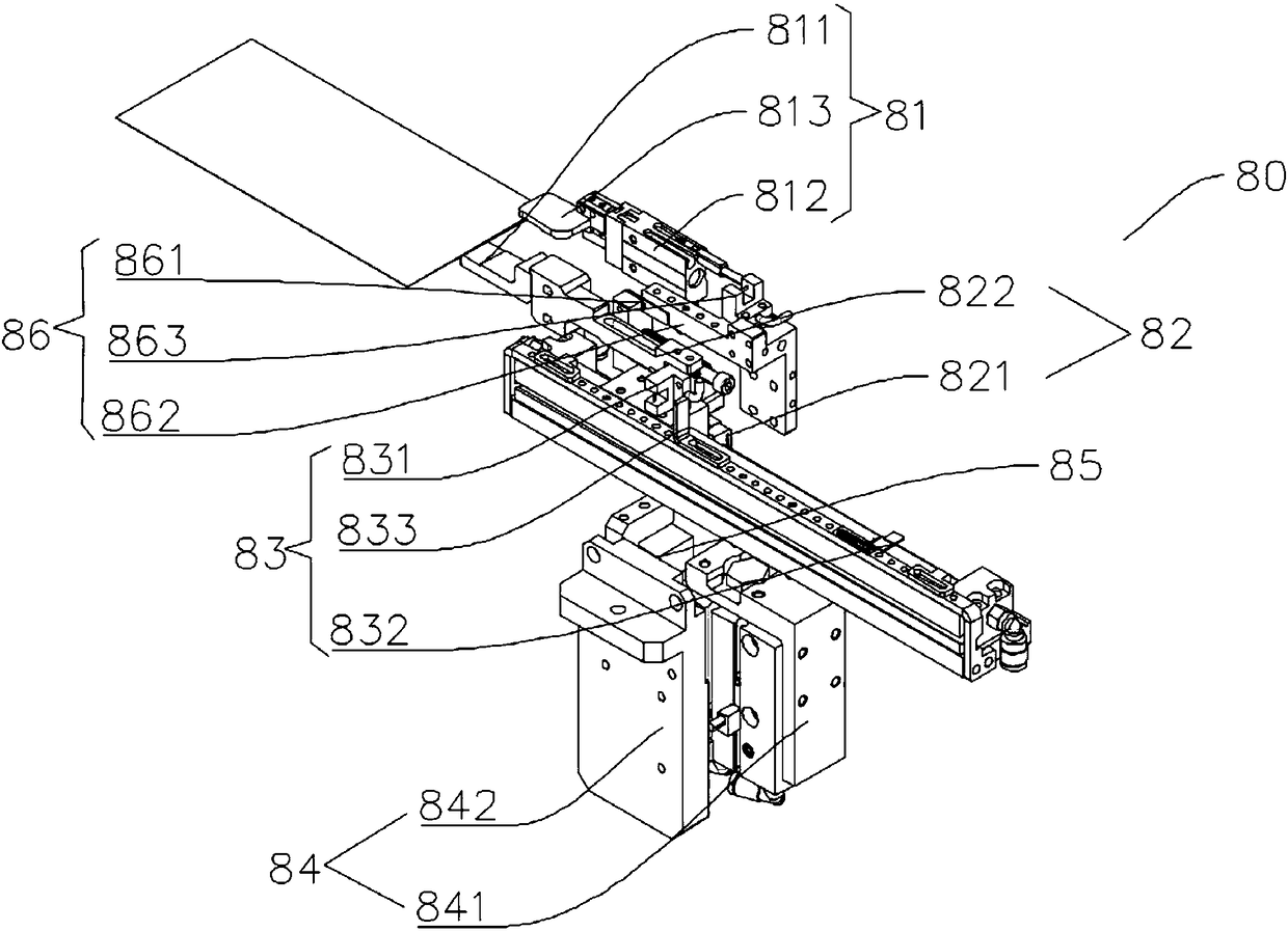
The invention discloses a feeding mechanism of a fluid coating device and the fluid coating device with the same. The feeding mechanism is used for supplying materials to a track conveying mechanism of the fluid coating device, and comprises a clamping device, a dragging device, a material blocking device and a driving device, wherein the clamping device can move so as to clamp or release the materials, the dragging device can move in the extending direction of the track conveying mechanism, the dragging device is connected with the clamping device so as to drag the clamping device, at least apart of the material blocking device is arranged on a moving path of the dragging device, the material blocking device controls the clamping device to release the materials and stop the materials soas to enable the materials to be separated from the clamping device when the dragging device moves to a preset position, the driving device is connected with the dragging device and the clamping device, and the driving device drives the dragging device and the clamping device to move up and down. The feeding mechanism of the fluid coating device is simple in structure, high in feeding speed and high in stability.

Description

technical field [0001] The invention relates to the field of fluid coating, and more specifically, to a feeding mechanism of a fluid coating device and a fluid coating device having the same. Background technique [0002] Because the existing online operation method is to transport the product to the inside of the cabinet machine through the conveying track for coating operation. When the process is not suitable for the connection, the machine needs to manually put the product from the entrance of the track, and then the product is transported to the working position by the track inside the machine for coating operation. One person can operate up to 2 machines, which cannot be automated. In addition, the structure of the feeding mechanism of the current cabinet type machine is complicated, and the assembly and operation are inconvenient. Contents of the invention [0003] The present invention aims to solve at least one of the technical problems existing in the prior art...

Claims


Application Information

Patent Timeline
IPC IPC(8): B05C13/00
CPCB05C13/00
Inventor 陈鹏张俊杰郜福亮
Owner CHANGZHOU MINGSEAL ROBOT TECH CO LTD
Why Eureka
Try Eureka