Electric vehicle controller mounting box

A technology of electric vehicle controller and installation box, which is applied in the direction of vibration suppression adjustment, electrical components, spring/shock absorber, etc., which can solve the problems of reduced service life of the controller, damage of the controller, and inconvenient use of the electric car, so as to guarantee the service life , Guaranteeing safety and ensuring high efficiency

Active Publication Date: 2021-11-16
JIUJIANG JINYING TECH
View PDF8 Cites 0 Cited by
  • Summary
  • Abstract
  • Description
  • Claims
  • Application Information

AI Technical Summary

Problems solved by technology

[0002] For example, the electric vehicle discloses: an electric vehicle controller installation box for an electric vehicle controller, and a model of an electric vehicle controller installation box is disclosed: a 96V controller, and the electric vehicle controller (controller) is a kind of electric vehicle controller. The installation box of the controller is the core controller of the vehicle. The electric vehicle controller has functions such as reverse charging, stall protection, dynamic and static phase loss protection, cruise alarm, high-speed control, mode switching, and follow-up abs system, but it is aimed at a kind of electric vehicle control The installation box of the device is used for electric vehicles on the roads of rural villages. Since most of the rural villages are dirt roads with potholes, when the tram is running on the road, the tram often vibrates due to the potholes on the road. The controller of the electric car is usually placed inside the electric car or fixed on the bottom plate inside the electric car, and then when the electric car is riding, the vibration will directly act on the controller, which will cause internal damage to the controller due to the vibration, which will cause control failure. The service life of the controller is reduced, and the controller is often damaged, which makes it inconvenient to use the tram.

Method used


Image

  • Electric vehicle controller mounting box
  • Electric vehicle controller mounting box
  • Electric vehicle controller mounting box

Examples


Embodiment 1

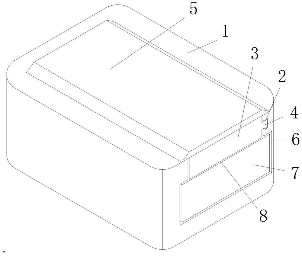
[0036] Example 1: See Figure 1-8, an installation box for an electric vehicle controller, comprising a placement slot 1, a card slot 2 is opened on the inner side of the placement slot 1, a sealing plate 3 is slidably connected to the inside of the placement slot 1, and a clamping plate is fixedly connected to the right side of the sealing plate 3 4. Both the shape of the card slot 2 and the card plate 4 are irregular, the surface of the card plate 4 is slidably connected inside the card slot 2, and the upper side of the sealing plate 3 is fixedly connected with a protective plate 5, and the shape of the protective plate 5 is Isosceles ladder shape, the lower side of the protective plate 5 is slidingly connected with the upper side of the placement groove 1, the inside of the placement groove 1 is provided with a chute 6, the inside of the chute 6 is slidably connected with the upper slide plate 7, and the upper side of the upper slide plate 7 An auxiliary groove 8 is opened,...

Embodiment 2

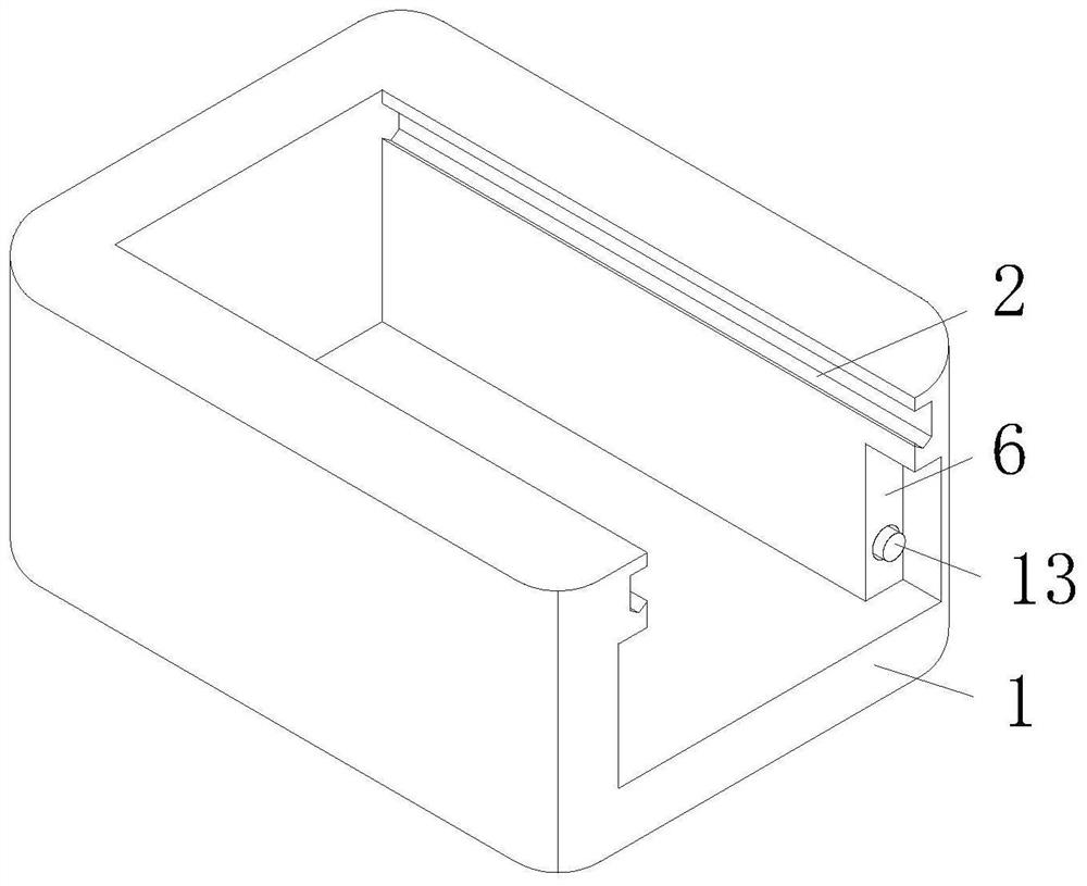
[0039] Example 2: see Figure 5 , on the basis of Embodiment 1, the cable arrangement device includes a connecting rod 9, the upper end of the connecting rod 9 is slidably connected to the inside of the upper sliding plate 7, the lower end of the connecting rod 9 is fixedly connected to the lower plate 10, and the surface sliding sleeve of the connecting rod 9 Connected with a tension spring 11, the upper and lower ends of the tension spring 11 are respectively fixedly connected to the lower side of the upper slide plate 7 and the upper side of the lower slide plate 10, and the lower side of the upper slide plate 7 and the upper side of the lower slide plate 10 are provided with wire grooves 12. The front side of the lower plate 10 is fixedly connected with a limit rod 13, and the front end of the limit rod 13 is slidably connected to the inside of the placement groove 1.

[0040] When in use, when the upper slide plate 7 is driven by the sealing plate 3 to slide and dock to t...

Embodiment 3

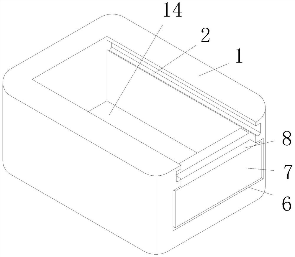
[0041] Example 3: See Figure 4-7 , the damping device includes a placement plate 14, the surface of the placement plate 14 is slidably connected to the inside of the placement groove 1, the lower side of the placement plate 14 is fixedly connected with a buffer rod 15, and the lower end of the buffer rod 15 is slidably connected to the inside of the placement groove 1, The surface of the buffer rod 15 is slidingly sleeved with a buffer spring 16, and the upper and lower ends of the buffer spring 16 are respectively fixedly connected to the lower side of the placement plate 14 and the inside of the placement groove 1, and the upper side of the placement plate 14 is slidably connected to a shock absorbing plate 17. , the upper side of the damping plate 17 is inclined, the surface of the damping plate 17 is slidingly sleeved with a damping spring 18, and the upper and lower ends of the damping spring 18 are fixedly connected to the surface of the damping plate 17 and the bottom o...


PUM


Abstract

The invention relates to the technical field of electric vehicles, in particular to an electric vehicle controller mounting box which comprises a placement groove. A clamping groove is formed in the inner side of the placement groove, a sealing plate is slidably connected to the interior of the placement groove, a clamping plate is fixedly connected to the right side of the sealing plate, a sliding groove is formed in the placement groove, and an upper sliding plate is slidably connected to the interior of the sliding groove. An auxiliary groove is formed in the upper side of the upper sliding plate, the lower side of the sealing plate is slidably connected with the interior of the auxiliary groove, and a wire arranging device is arranged on the lower side of the auxiliary groove. Compared with the prior art, the village road is relatively large in depression, so that the electric car is greatly vibrated during movement, the controller in the placement groove has a timely buffering effect after the electric vehicle is vibrated, the use safety of the controller is guaranteed, the service life of the controller is also guaranteed, and the defect that the controller is damaged due to vibration easily caused by a rural road is avoided.

Description

technical field [0001] The present application relates to the technical field of electric vehicles, in particular to an installation box for an electric vehicle controller. Background technique [0002] For example, the electric vehicle discloses: an electric vehicle controller installation box for an electric vehicle controller, and a model of an electric vehicle controller installation box is disclosed: a 96V controller, and the electric vehicle controller (controller) is a kind of electric vehicle controller. The installation box of the controller is the core controller of the vehicle. The electric vehicle controller has functions such as reverse charging, stall protection, dynamic and static phase loss protection, cruise alarm, high-speed control, mode switching, and follow-up abs system, but it is aimed at a kind of electric vehicle control The installation box of the device is used for electric vehicles on the roads of rural villages. Since most of the rural villages a...

Claims


Application Information

Patent Timeline
Patent Type & Authority Applications(China)
IPC IPC(8): H05K5/00F16F15/067
CPCH05K5/0073H05K5/0056F16F15/067
Inventor 黄明黄彬
Owner JIUJIANG JINYING TECH
Why Eureka
Try Eureka